Class 6: 3D Design & Printing
LOOK AT BOTTOM FOR UPDATES ABOUT PRINTING
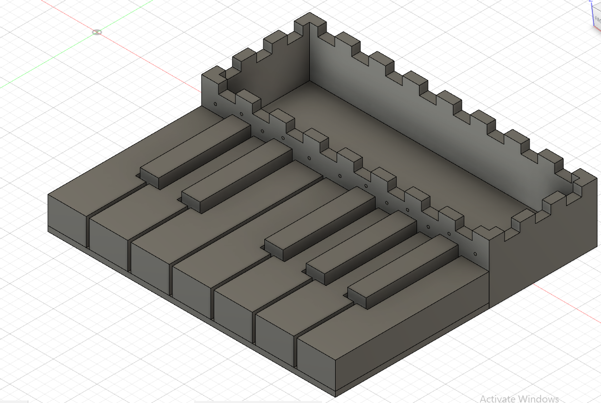
The first part of the assignment for this class was to design and prepare to print a component I need for my final project. For my final project, I'm making a keyboard that will use copper tape and a buzzer to make sound, so I knew that almost my entire project would need to be 3D printed. The first thing I did was find this set of piano keys on Thingiverse. I then imported it into Fusion 360 and, since it was imported as a mesh body, retraced it to make it a regular body, which made editing it significantly easier. I knew that I was going to have a box containing my microcontroller, buzzer, and buttons (to change the octave) behind the keyboard, so I modeled a platform under the keyboard to hold the keys and box together. Once I was happy with that, I made the box that would hold my other components. I used the user parameters to set the dimensions of the box and then extruded it to the necessary height. Once I had the height set, I used the shell tool to hollow out the box, making room for the microcontroller. Next, I used my caliper to measure the diameter of the wires that I would be using to connect my copper tape to my microcontroller, added it to my user parameters, and then added holes above each key. Once I had the holes, I extruded them the depth of the box using the Extrude To tool. the next step was to make a gear-like pattern on the top of the box so that I could fit a roof, making it easy to remove, as I knew that I would want to ensure I could take it apart to fix things or make changes. I practiced a bit with the Rectangular Pattern tool before attempting this so that I could make sure I did it right. On the shorter face of the box, I made a rectangle that was 1/7 the width of the box long and the depth of the box wide. The reason I did the depth of the box for the dimension is because I did a lot of thinking, and I realized that the roof would need to fit well with the rest of the box, meaning the depth of the roof should equal the width of the rectangle, to ensure a proper fit. I then the used the Rectangular Pattern tool to copy and paste the rectangle 7 times, completely filling the width of the box. I then duplicated this on the other shorter face. Next, on one of the longer faces, I made a rectangle that was 1/17 the length of the box long and, again, the depth of the box wide. I then used the Rectangular pattern tool to completely fill the top of the face with rectangles, just like before, and then duplicated this on the other face. I then used the Extrude To tool to cut out the holes to fit the roof. I learned a lot through this process, specifically with the rectangular pattern tool, as I struggled to properly space the rectangles in the beginning. It was a lot of trial and error, but I'm glad I put in the time to really learn how to use it, as it made making the roof significantly easier.
Here's an image of the final piano and box:
Here are the links to the piano and box files, both in Fusion 360 and for 3D printing:
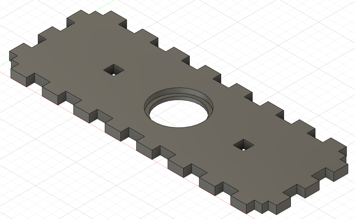
After making the piano and box, I modeled the roof of the box next. I used user parameters to make the dimension of the roof the same as the dimensions of the box face it would attach to. Next, I performed the same rectanglar patterns that I did for the other box, except now I was doing both the shorter and longer face patterns on the same sketch. Thanks to what I learned doing the rest of the box, this part of the roof went significantly quicker and I worked more efficiently. After I had all of the rectangles, I extruded it the depth of the box, like before, but this time I extruded all the rectangles that I didn't extrude in the box. That way, where the box had holes, the roof wouldn't, and vise versa. Doing so would allow the roof to fit perfectly in the rest of the box. Once I was finished with that, I had to make the holes for the buzzer and buttons. I first used construction lines to locate the exact center of the roof, and the made a circle that was 26 mm, 4.5 mm less than the diameter of the buzzer. I made it smaller because I wanted the buzzer to lie on the roof without falling through. Once I extruded it the depth of the roof (to allow the pins of the buzzer to fit), I made another circle, this one 30.5 mm (0.5 mm more than the diameter of the circle). I made it a bit bigger because, through watching previous tutorials for the other classes, I knew that I wanted a bit of wiggle room. I then moved on to making holes for the buttons. I used constructon lines to mark a point 25 mm to the right of the rightmost point of the circle, and then used my user parameters for the button length to make a square. Since the button has pins on the edge, I was unable to to the same smaller/larger square extrusion that I did with the buzzer. Instead, I decided it would be best to fit the button in the hole and then hot glue the bottom of it to the roof, ensuring it would stay. Because of this, I extruded the depth of the face, making a hole in the roof. I then repeated this on the other side of the buzzer hole for the other button. Once this was done, I made it a component and put it in the piano file, as I've learned that it's best to test the dimensions to make sure they would fit. The roof fit perfectly. I learned a lot with this model as well, specifically about how it's best to not do exact dimensions (like with the circle), as there should be a bit of wiggle room to make sure everything fits properly.
Here's an image of the final roof:
Here are the links to the roof files:
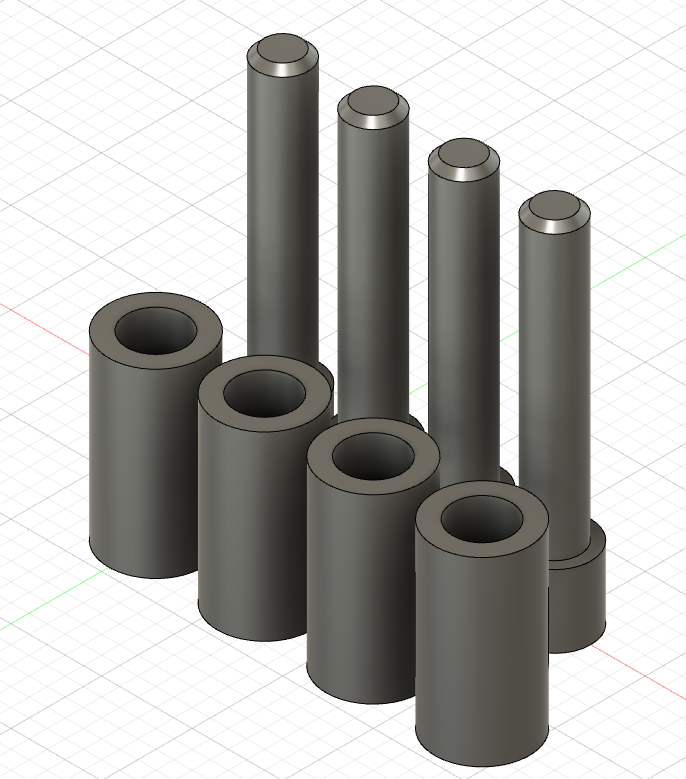
After making the roof, I modeled the pins for the microcontroller next. I remembered from watching the arduino enclosure tutorial last class that it's better to not let your microcontroller touch the ground. However, since I don't know the exact dimensions of my microcontroller, I decided it would be best to 3D print the pins and attach the via hot glue later. I first measured the diameter of the microcontroller's holes, which was 3.2 mm. Following along with the tutorial, I first sketched a circle that was 2.8 mm (again, allowing for some wiggle room). I then extruded that 20 mm. Next, I made another sketch, this time with a circle that was 3.2 mm, the dimension of the holes in the microcontroller. This was so that I could fit it through the smaller cylinder and have it rest on this larger one. I then extruded that 4 mm, per the tutorial's suggestion. Once the whole thing was extruded, I chamfered the top of the pins to allow the microcontroller to easily slide on. Once I finished these pins, I added in hollow cylinders (that I will attach to the roof) for the other pins to slide into, preventing the microcontroller from falling out.
Here's an image of the final roof:
Here are the links to the microcontroller holder pins files:
Overall, I learned a lot during the 3D modeling part of this assignment. Whether it be the rectangular pattern, shell, and extrude to tools, or just the general process of taking more effecient steps to make the models, I feel much stronger working with Fusion 360 than I did coming into the week.
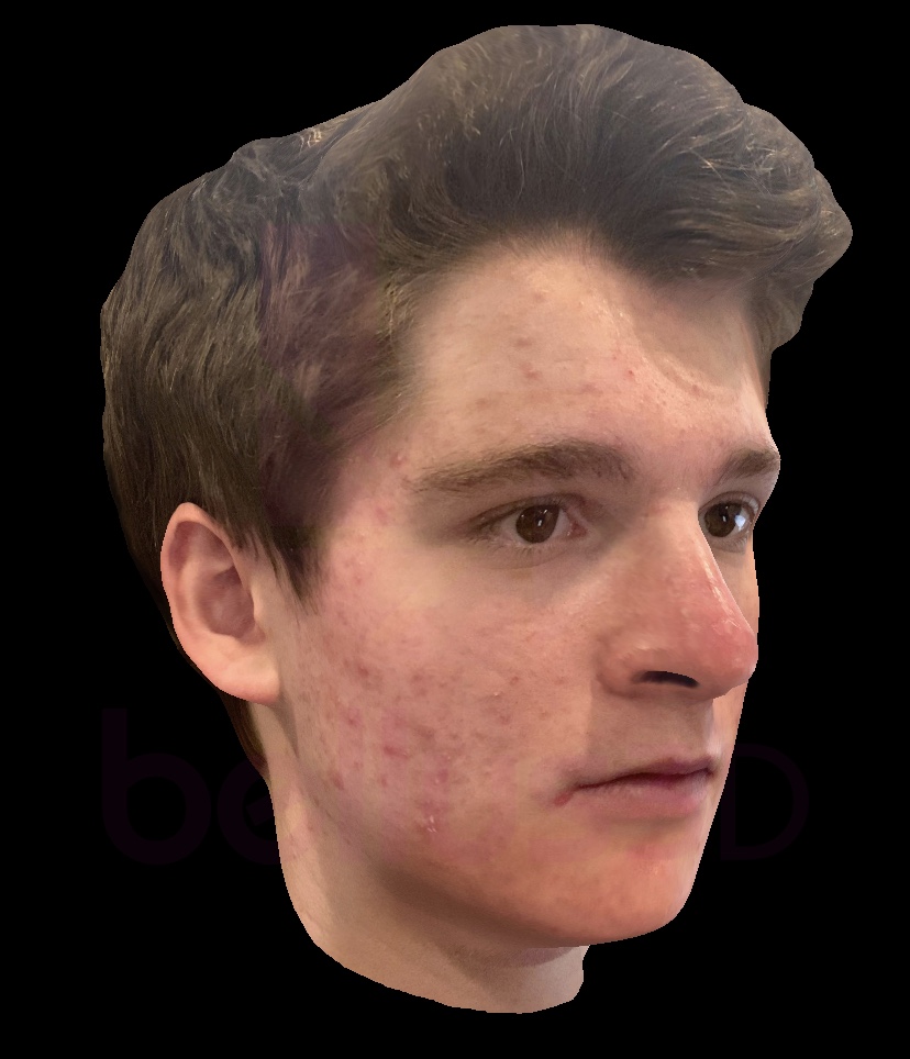
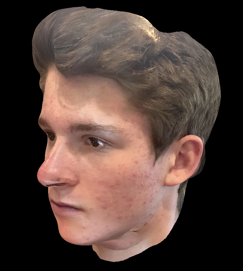
The second part of the assignment was to scan something using a photogrammetry application. I chose to use Bellus 3D to scan my face. Luckily, I got it to look good right on the first go! The app is fascinating; I was really impressed by how quickly it could create the model.
Here's the result:
UPDATE
After talking with Nathan and Victoria, we decided it would be best for me to laser cut most of my parts instead, as printing them would take over 18 hours and be at high risk of error. Here's what I need to laser cut:
- The white keys (in a white material): White_Keys.dxf
- The black keys (in a black material): Black_Keys.dxf
- The box: Box_Final.dxf
- The platform: Platform.dxf
However, I still need to 3D print the microcontroller holder pins. Here are the links again: