Class 7: Electronic Input Devices
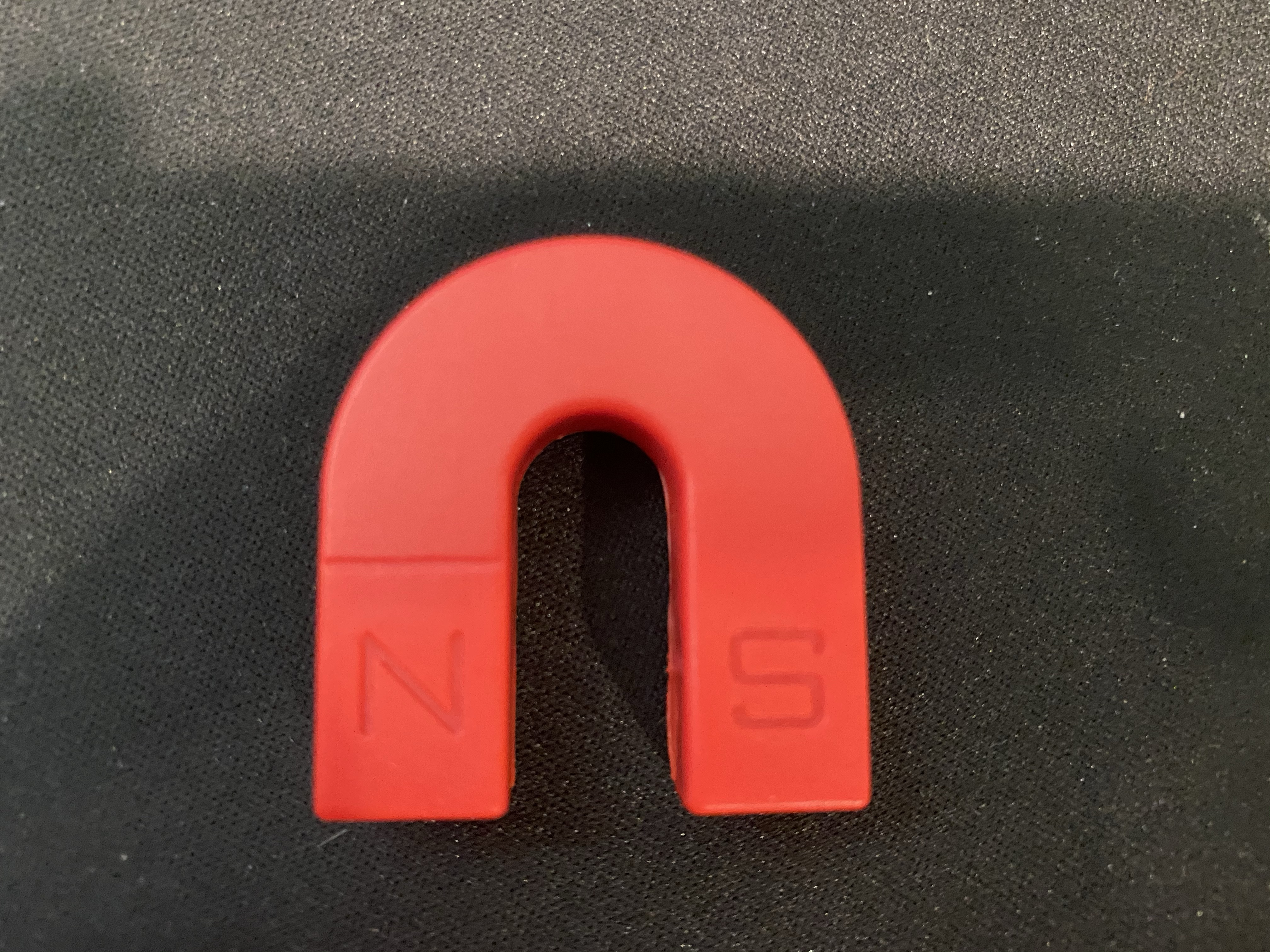
The first part of the assignment for this class was to use a sensor from the kit to measure a physical quantity with the Arduino. I also had to calibrate the sensor, which means describing the range between its min and max values and whether I can control this range. Lastly, I needed to show data in the form of a table or graph. I chose to use the Hall sensor, like Mr. Hart did, because I wanted to use his demo to get a better understanding of sensors and how they worked. Also, I used a horseshoe magnet from a small magnet kit I had as a little kid, and I wanted to see the difference in results between my magnet and Mr. Hart's. I set up my circuit as seen below:
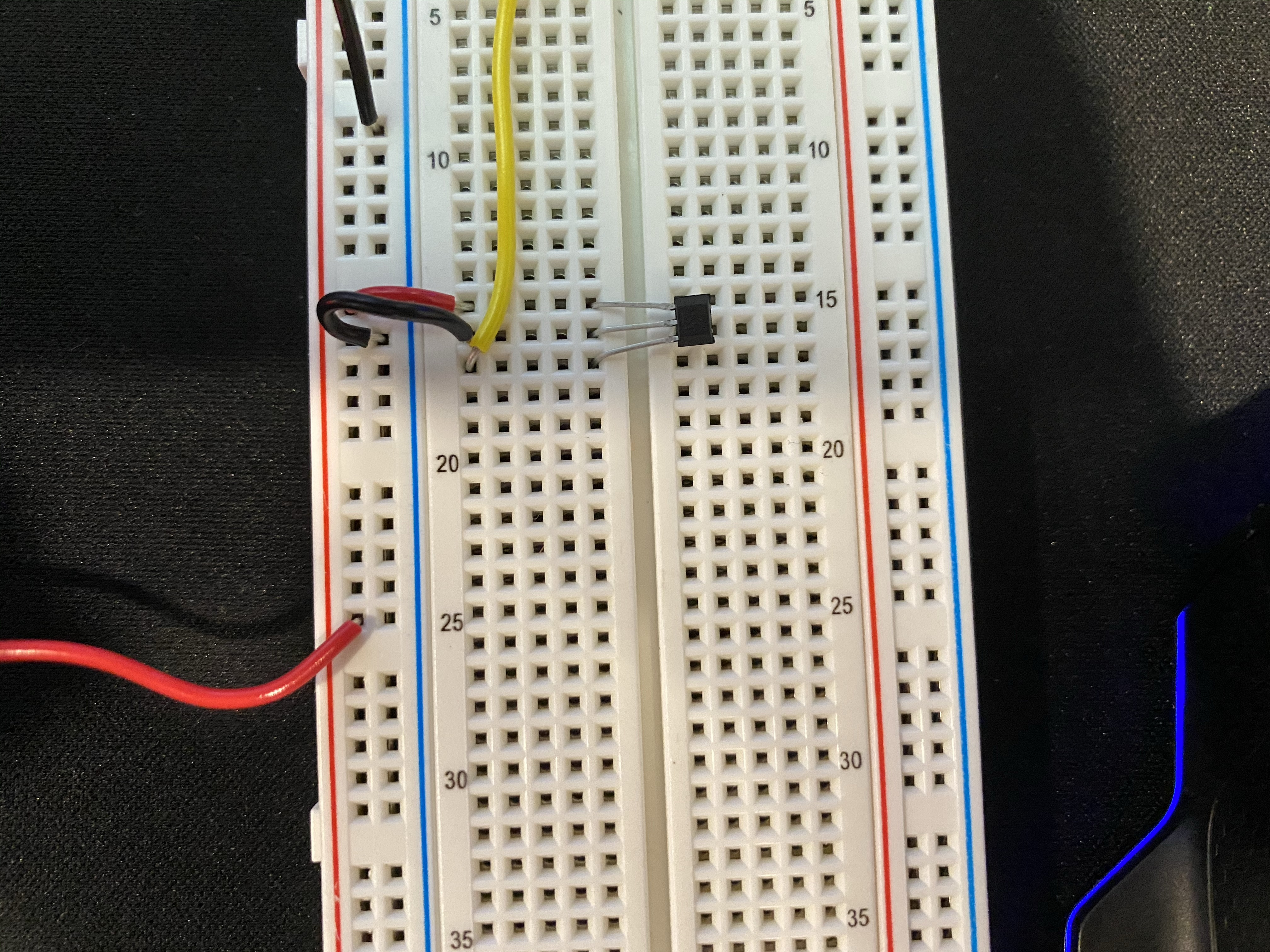
After setting up my circuit, I used the Arduino IDE to code Serial communication that would print the sensor value. When I ran this with no magnet, just the circuit plugged in, the reading was at around 503. The code I used can be seen below:
      void setup() {
        //Initialize serial communication at 9600 bits per second:
        Serial.begin(9600);
      }

      void loop() {
        //Read the input on analog pin 0:
        int sensorValue = analogRead(A0);

        Serial.println(sensorValue);
        delay(10);  // delay in between reads for stability
      }
I then calibrated the sensor by holding my magnet at various distances and recording my results. Unlike Mr. Hart, who used cardboard as spacers between the magnet and sensor, I used index cards. I added stacks of 6 at a time, which was the same as adding 1 mm. Additionally, I wanted to flip the magnet between the North and South sides each time I recorded a measurement. I predicted that the S would be above 503 and the N would be below 503. This is the table of values I obtained at different distances away from the sensor:
| Distance from Sensor (mm) | Serial Output (South) | Serial Output (North) |
|---|---|---|
| 0 | 1001 | 5 |
| 1 | 977 | 20 |
| 2 | 825 | 160 |
| 3 | 780 | 230 |
| 4 | 700 | 300 |
| 5 | 659 | 340 |
| 6 | 602 | 392 |
| 7 | 595 | 400 |
| 8 | 580 | 420 |
| 9 | 565 | 441 |
| 10 | 553 | 454 |
And here's a graph of these values:
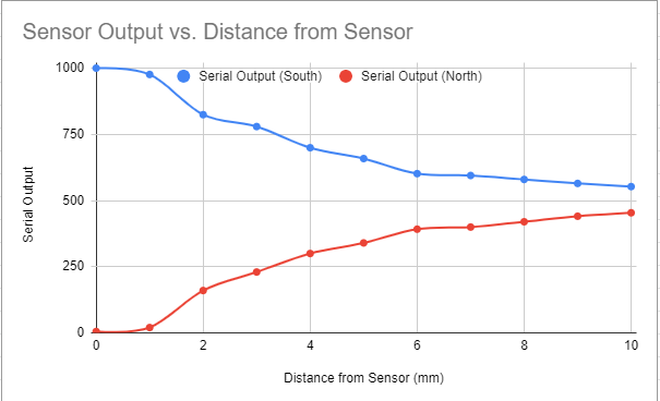
Based on my results, I realized that Mr. Hart must have been using the north side of his magnet, as his numbers increased as the distanced increased, just as mine did for the north side. I also noted that the increase for the north side and decrease for the south side were very similar each time compared between the current value and previous value, which makes sense, as the magnet is nearly equal strength on each side. Of course, there was probably some error in my measurements, but I don't belive there was enough to make my data inaccurate. I learned a lot about sensors through this first exploration, as I had no idea how the sensor worked beforehand. It was interesting to see how the range varied from about 5-1001, with a no magnet reading almost exactly in the middle. I also noticed that the sensor is most sensitve between distances of 0 and 4 mm, as those had the biggest differences in readings from the prior measurement.
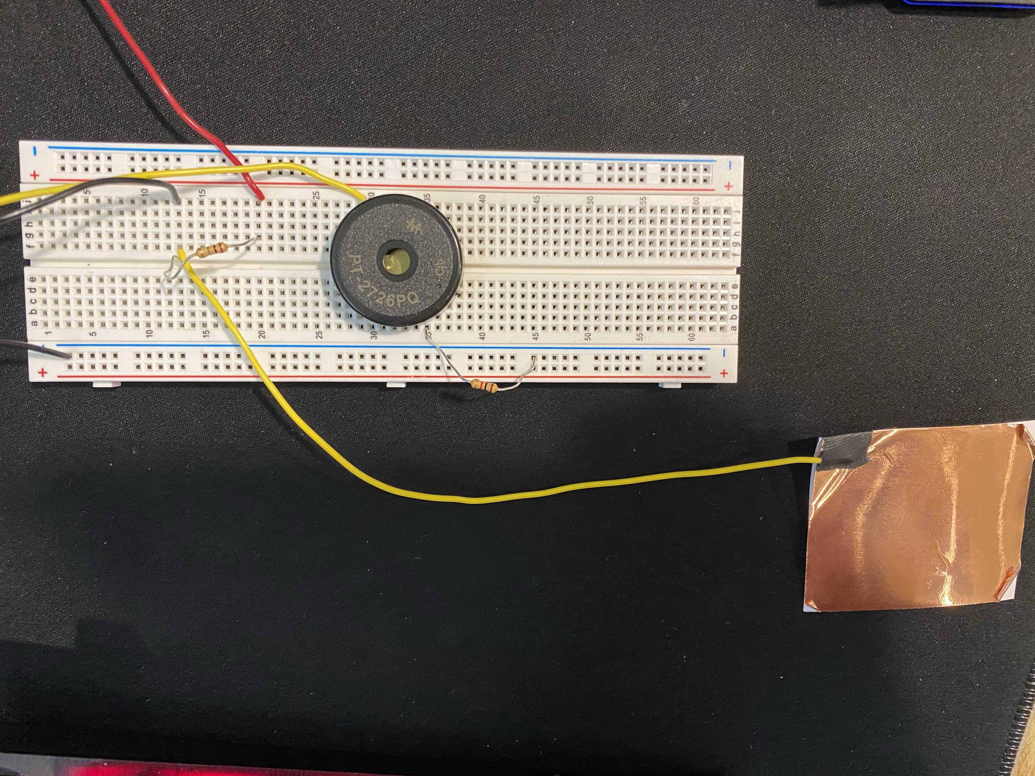
The second part of the assignment was to do the same as part 1 but this time with a sensor I fabricated myself. Since my final project is going to be making a piano using copper tape and a buzzer, I wanted to do more than just measure a physical quality, I wanted to actually produce a sound. To do this, I implemented a buzzer and copper tape into my circuit. I wanted the copper tape to sense my hand, so I linked the copper tape to pin 5 and pin 7, and connected those wires using a 1 megaohm resistor. Next, I connected a buzzer to pin 9 and used a 1K ohm resistor to ground it. The result of this circuit can be seen below:
After making the circuit, I knew that I would have to add code for the Capacitive sensor (the copper wire) and the buzzer. I read Nathan's tutorial about buzzers to learn about how the buzzer worked, specifically about producing sound using the tone function. I learned a lot about how the buzzer works. Since I'm making a piano, I wanted to press the tape and have it play a predetermined note, in this case a C. I used this example code to figure out the frequency of the C note. Once I had a better understanding of the buzzer, I produced this code to both print the Serial Output number and play a C if the tape was touched:
      #include
      const int C = 261;
      int buzzerPin = 9;
      CapacitiveSensor Sensor = CapacitiveSensor(7, 5); //7 is charge pin.  5 is sense pin.

      void setup() {
      Serial.begin(9600);

      //Setup pin mode
      pinMode(buzzerPin, OUTPUT);
      }

      void loop() {
        long sensorValue = Sensor.capacitiveSensor(10000);      //Change the number of samples to get the required timing and sensitivity.
        delay(10);
        Serial.println(sensorValue);

        if (sensorValue > 1000) {
          tone(buzzerPin, C, 100); //play tone
          delay(10);
        }
      }
For some reason, no matter what I tried, I couldn't get the copper tape to sense my hand unless I was touching it. I was originally disappointed, as I wasn't able to make a graph or table like in the previous example. But, I soon realized that this is actually ideal, as I'm making a piano that should only play a note when the key is touched.
Here's a video of the buzzer in action!