Final Project: Mini Piano
Note: Please excuse the poor quality of this website. I was only 16 when I made it and had not used HTML or CSS prior to this course.
Video Demonstration:
Why I Chose This Project:
Not only do I love music, but I've been an avid piano player since I was five years old and, to this day, it's one of my favorite hobbies. When I was thinking of ideas for my final project, I wanted to apply the mechanical knowledge I had learned to something enjoyable in my daily life, so a piano was one of the first things I brainstormed. After a couple initial ideas (that used clunky, actual keys), I decided to use copper tape to sense touch, which was a significantly better idea. In the end, I'm really happy with how it turned out.
How It Works:
- Copper tape electrically senses touch and the buzzer plays a note corresponding to the key that was pressed
- Each piece of copper tape is connected to a sense pin, which the code uses to determine which note was pressed
- Every 3 pieces of tape have resistors soldered together that connect to a charge pin
- The left button decreases the octave by 1 and plays Mozart's Rondo Alla Turca when double clicked
- The right button increases the octave by 1 and plays Happy Birthday when double clicked
Designing the Components:
The first part of the process was to design the piano's components in Fusion 360. Below is information about how I designed each component.
The Keys:
The first thing I did was find this set of piano keys on Thingiverse. Knowing that it would be easier to laser cut keys rather than 3D print them, I took the original key design from Thingiverse and retraced it to give me more design freedom. This was a necessary step since I imported the keys as a mesh body, which was extrememly difficult to edit, plus it wouldn't work for laser cutting. Once I had the keys traced, I was ready to export the design to be laser cut. Here's how the final design turned out:
However, I needed to split up the black keys and white keys for laser cutting, as they would be cut in different colors. While designing the keys, I had made the white keys their own sketch and the black keys their own sketch. From there, I exported each as a .dxf file to prepare them for laser cutting. Here are the .dxf files for the piano keys:
- White keys DXF: White Keys
- Black keys DXF: Black Keys
With the keys done, it was time to move onto designing my next component.
The Box:
I knew that I would need a box to fit all of my wires, the metro, the buzzer, and the buttons. I utilized a resource called Makercase, which automatically creates a box exactly like the one I needed. On the website, I input the dimensions for my box. Since my piano keys totaled 165 mm in length and the Metro microcontroller is about 54 mm wide, I input the dimensions for my box as 165 mm x 25.5 mm x 62 mm. Once that was finalized, I downloaded it as a .svg and inserted it into Fusion 360. Next, on the front face, I added twelve 1.5 mm holes for each piece of copper tape (1 piece of tape per piano key). And on the top face, I added a circular hole in the middle for the buzzer and two square holes on either side of the buzzer for the buttons. Once that was completed, the design was finished. Here's how the final design looked:
At this point, I was ready to laser cut the box. I exported it as a .dxf and sent it over to the instructors. Here is the .dxf file for the box:
- Box DXF: Box
Now that the box was finished, I moved onto the next component of my project.
The Microcontroller Holder Pins:
I remembered from watching the arduino enclosure tutorial for homework that it's better to not let your microcontroller touch the ground. I measured the diameter of the metro's holes (3.2 mm). In Fusion360, I first sketched a circle that was 2.8 mm (allowing for some wiggle room). I then extruded that 20 mm. Next, I made another sketch, this time with a circle that was 3.2 mm, the dimension of the holes in the microcontroller. This was so that I could fit it through the smaller cylinder and have it rest on this larger one. I then extruded that 4 mm, per the tutorial's suggestion. Once the whole thing was extruded, I chamfered the top of the pins to allow the microcontroller to easily slide on. Once I finished these pins, I added in hollow cylinders (that I have resting on top of the metro) for the other pins to slide into, preventing the microcontroller from falling out. Here's the final design for the pins:
Here are the links to the microcontroller holder pins files:
With the pins completed, I had one small component left to design.
The Platform:
Since each key was cut individually, I knew that I needed a platform on which I would glue all of the keys. This was a very simple design, as it was just a rectangle long and wide enough to fit the keys. Since I knew the keys totaled 165 mm and each key was 88.2 mm wide, I made the dimensions of the platform 165.5 mm x 88.7 mm to ensure adequate space. Here's how the design turned out:
At this point, I was ready to laser cut the box. I exported it as a .dxf, which can be found below:
- Platform DXF: Platform
Designing the Circuit:
The next part of my project was designing the circuit. I thought it would be easy to just plug in the copper tape but soon realized it was much more complicated that that. Since each piece of tape needs to connect to both a charge pin and a sense pin, it seemed like I would need 24 pins for the 12 pieces of tape, plus an additional three pins for the buzzer and buttons. This was a big issue: the Metro only has 20 pins. I talked to Nathan, and he told me that it was possible to wire multiple pieces of tape to one charge pin. I knew I would need to solder wires together to do so, and I'll explain more about that in the Build Process section. To make sure I knew how the circuit would work, I made a preliminary sketch consisting of just two keys that shows how they connect to one charge pin, which looked like this:
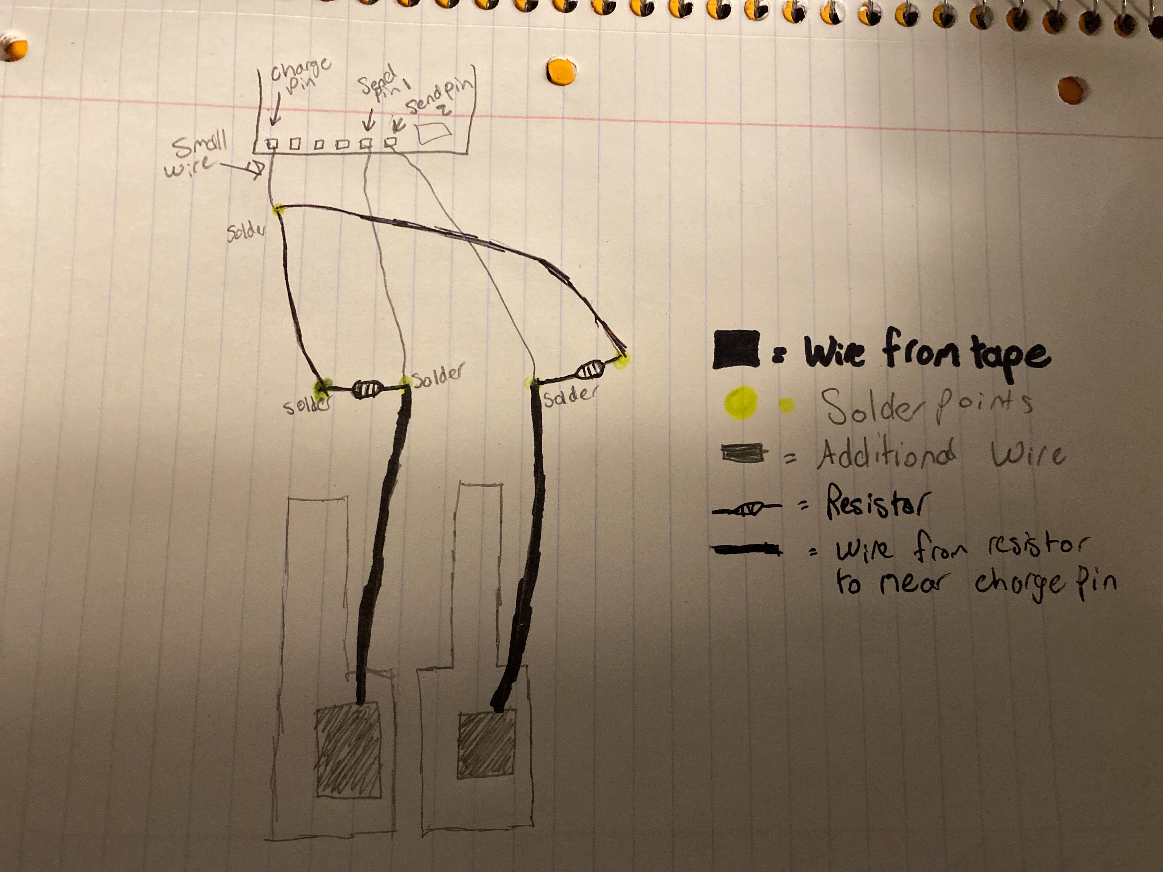
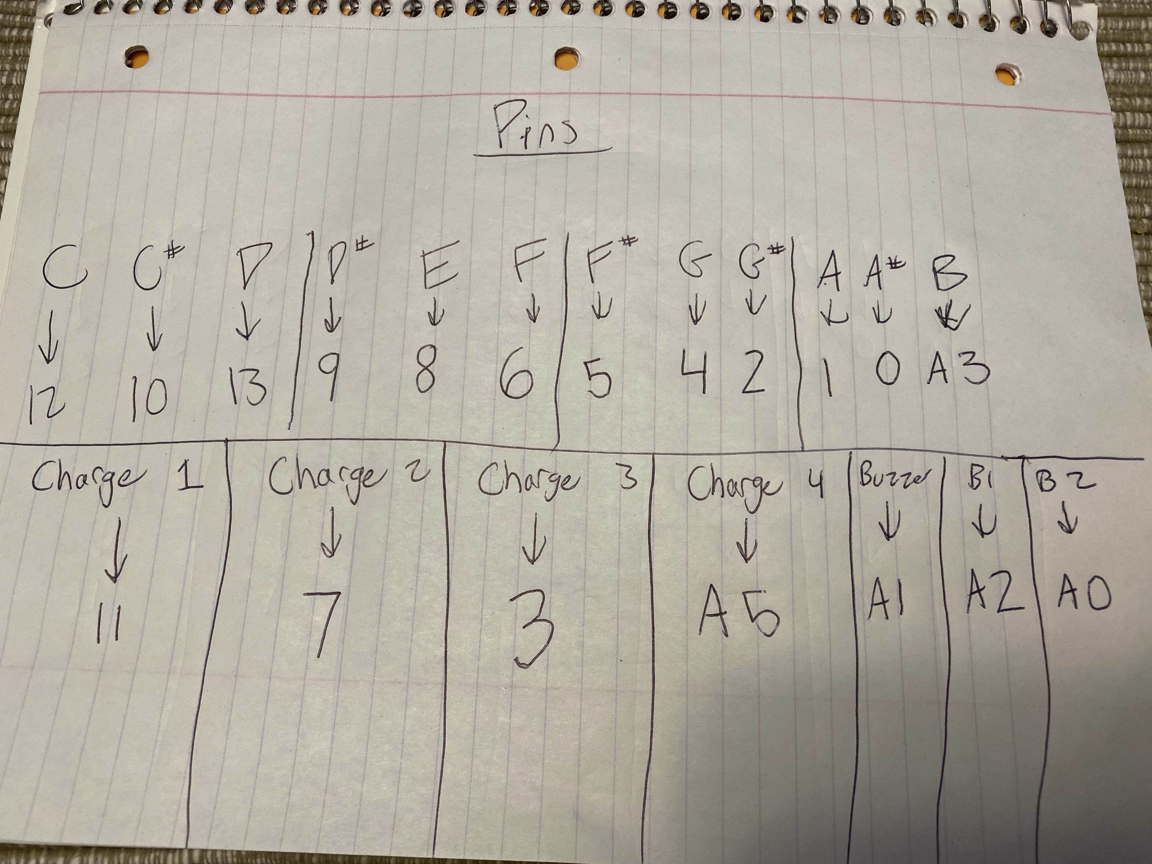
With the circuit sketch completed, I knew how the entire thing would be wired. But I had two things left to decide: 1) How many keys would be connected to one charge pin and 2) Which wire would go to each pin. I started by thinking about how many keys I should connect to each charge pin. I knew that I had a total of 20 pins, 12 of which were send pins for the keys and 3 of which were for the buzzer and buttons, leaving me with 5. Since I had 12 pieces of tape, I decided to split them up into groups of 3 and have 4 charge pins, as I didn't want to have to solder too many wires together, which could've been risky. Next, I wanted to write out where each wire would be plugged in before I started building to make the wiring easier. I decided that since I was going to have a large amount of wires, it would be best if I positioned the metro so that pins 0-13 were facing away from the keys (more about that in the Build Proecess section). Once I had that figured out, I wrote a list of where each wire would connect, for organizational and clarificational purposes. This was the final list:
At this point, I knew how the whole circuit would work, and it was time for the hardest part: building and wiring the piano.
The Build/Wiring Process:
Building and wiring the entire piano was the longest and most difficult part of the entire project. Beacuse of that, I've broken this section up into smaller subsections to better explain the whole process.
Attaching the keys:
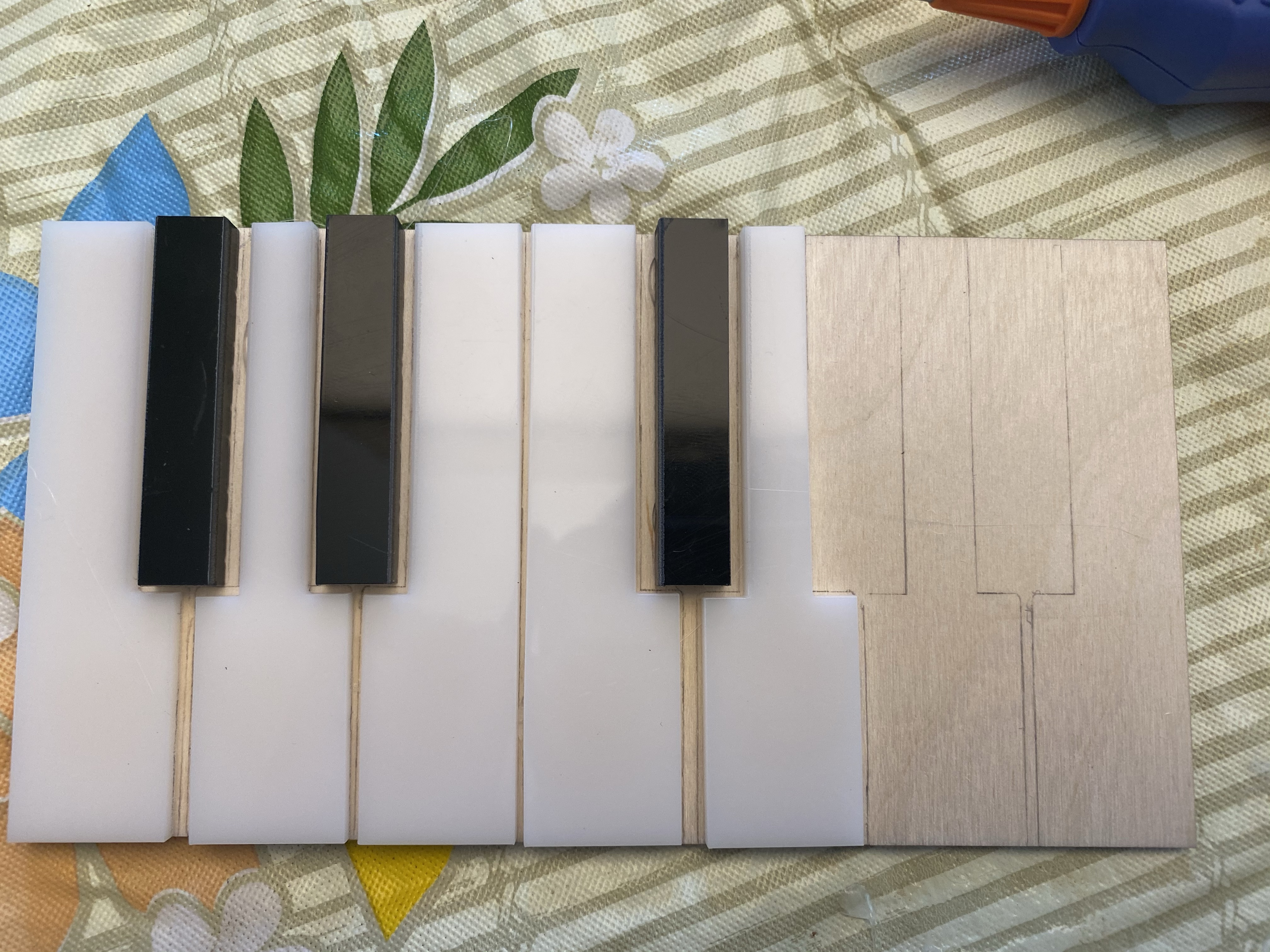
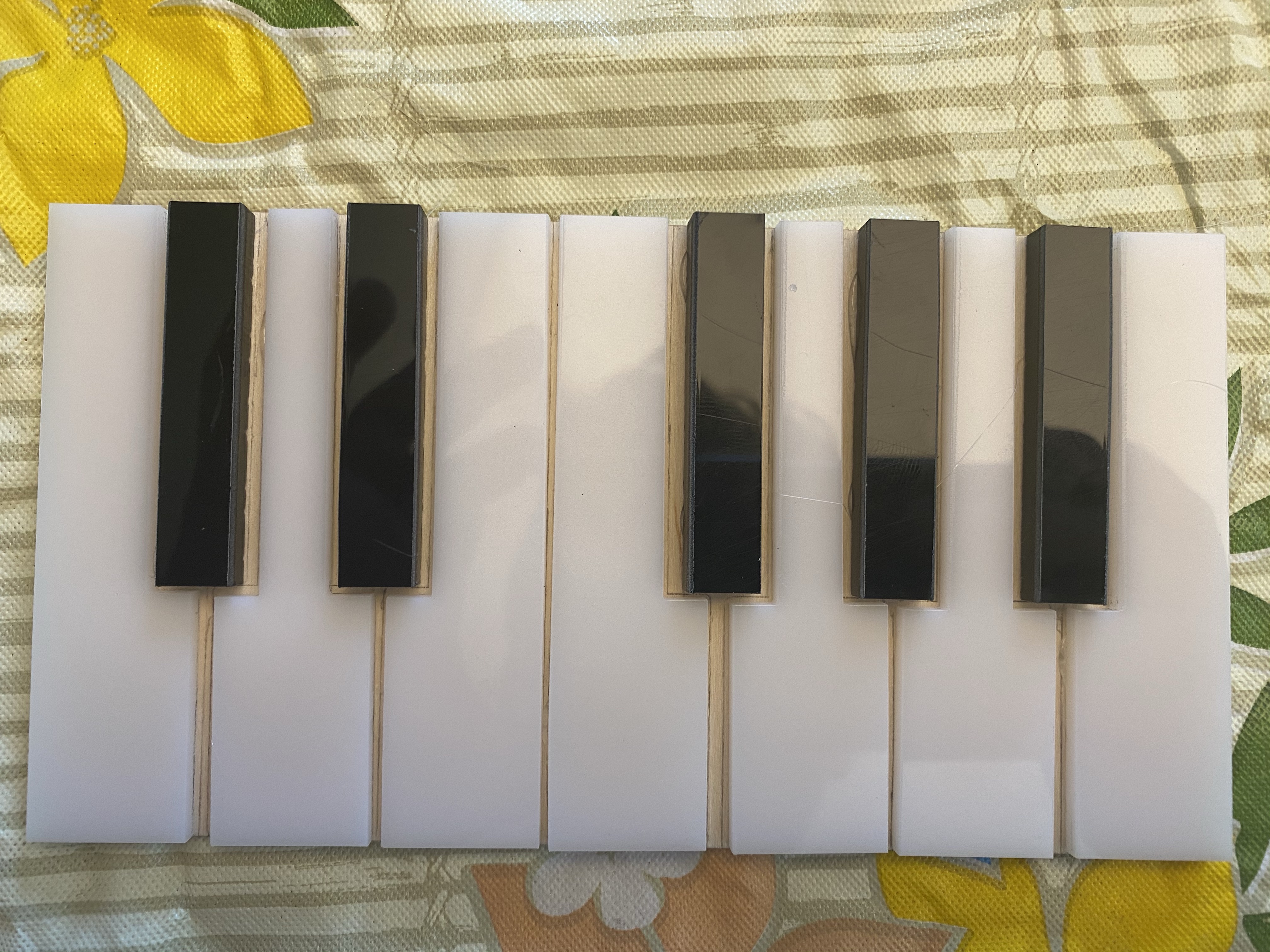
The first thing I did for building my piano was gluing the keys onto the platform. Initially, I sketched out in pencil how I would glue each key down. Once that was done, I used my hot glue gun to glue the keys. Below is a picture of the gluing just over halfway through and then another at the end.
Once I finished gluing down the keys, I decided to test my circuit with only three keys to make sure it worked before committing to all twelve keys.
Testing Three Keys:
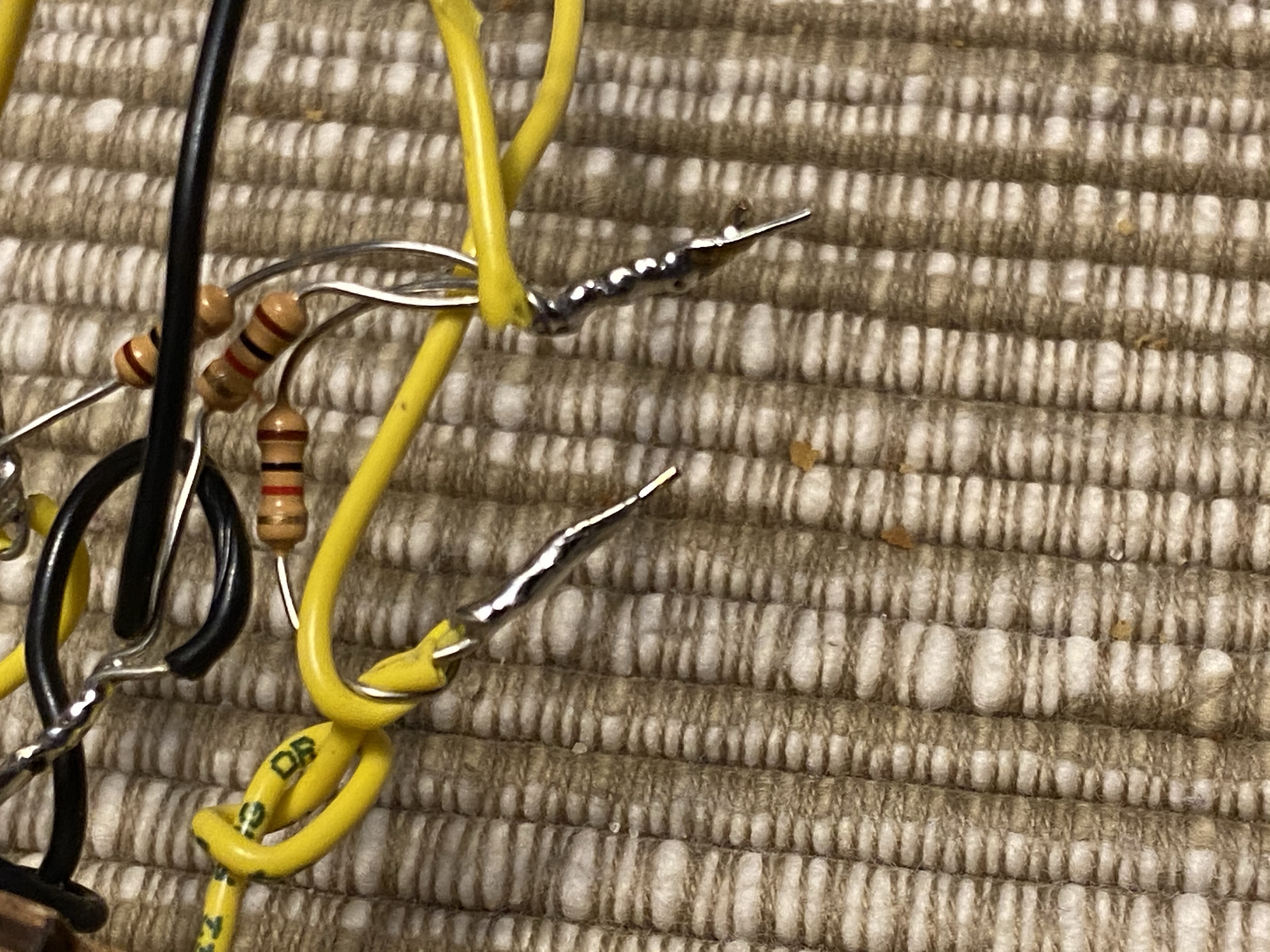
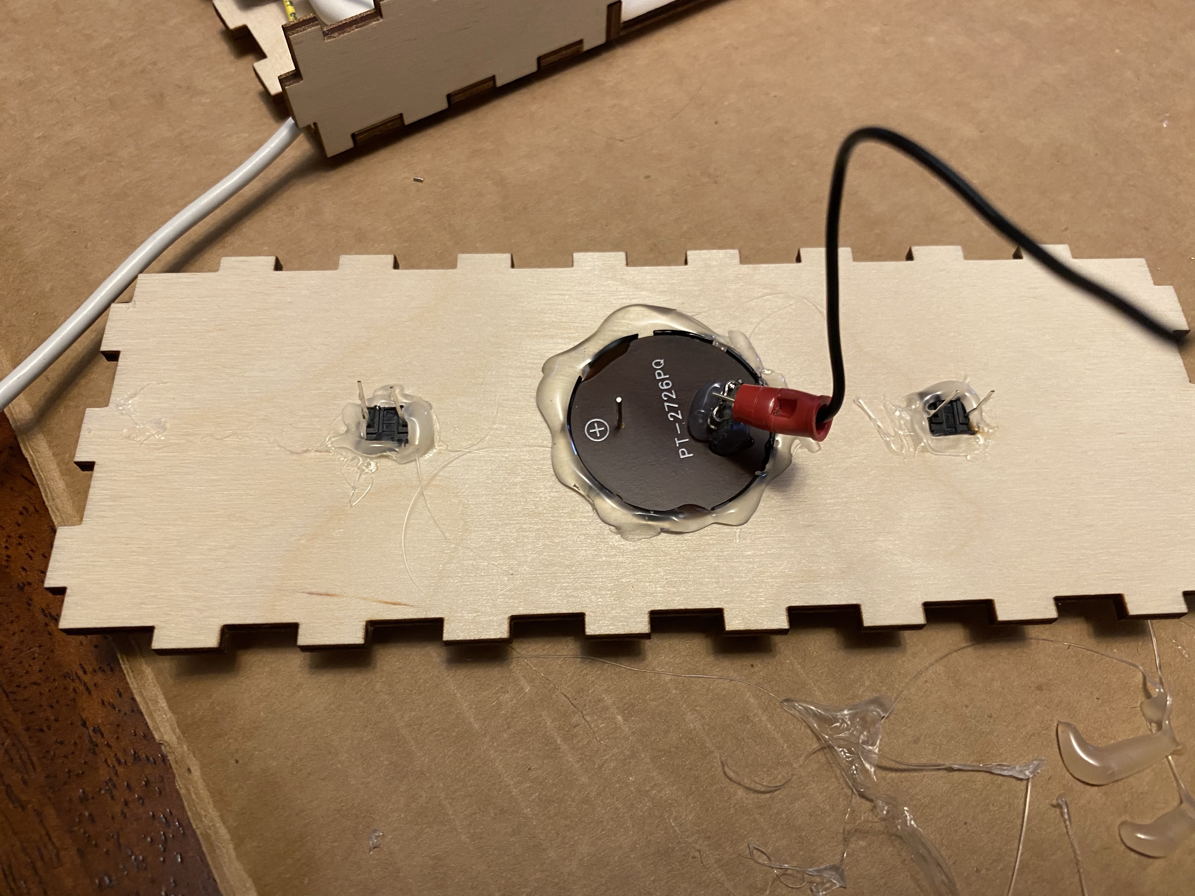
Testing my circuit with just three keys required me to solder wires together, something I've never done before. I watched this tutorial on how to solder. Luckily, my grandfather is a retired mechanical engineer, so I used his old soldering iron that I found in my basement. I first cut out the pieces of copper tape that I would use on these three keys. Two pieces of copper tape came with wires already soldered on, so that wasn't an issue. When it came to the third piece of tape, I had to do my first bit of soldering. I did some practice with spare wire beforehand so that I felt more comfortable when working with the tape. Once I soldered a wire to the copper tape, I covered it with a piece of black tape, just like the pieces in my kit. One I had all three pieces of tape ready with wire, I taped them down to the first three keys and stuck the wires through the holes in the front of the box (it was still unassembled at this time). Once the wires were stuck through the box it was time for the heavy-duty soldering. For the first key, I grabbed a 1k Ω resistor and another wire and twisted both together with the wire coming from the tape. Once they were twisted together, I soldered them together. I then repeated this process for the other two keys. After completing this, I twisted the three resistors together with another wire and soldered them all together (this was the wire that would go to the charge pin. The result of the soldering looked like this:
Once I had finished the wiring for the first three keys, I plugged the wires into my Metro and used some code I'd written to test out playing the notes (I'll explain more about the code in the code section). To my delight, the initial test worked well! I was able to touch the copper tape and have it produce the correct note. I was really happy with this, and then moved onto the next part of the build: gluing together the rest of the box.
Building the Box:
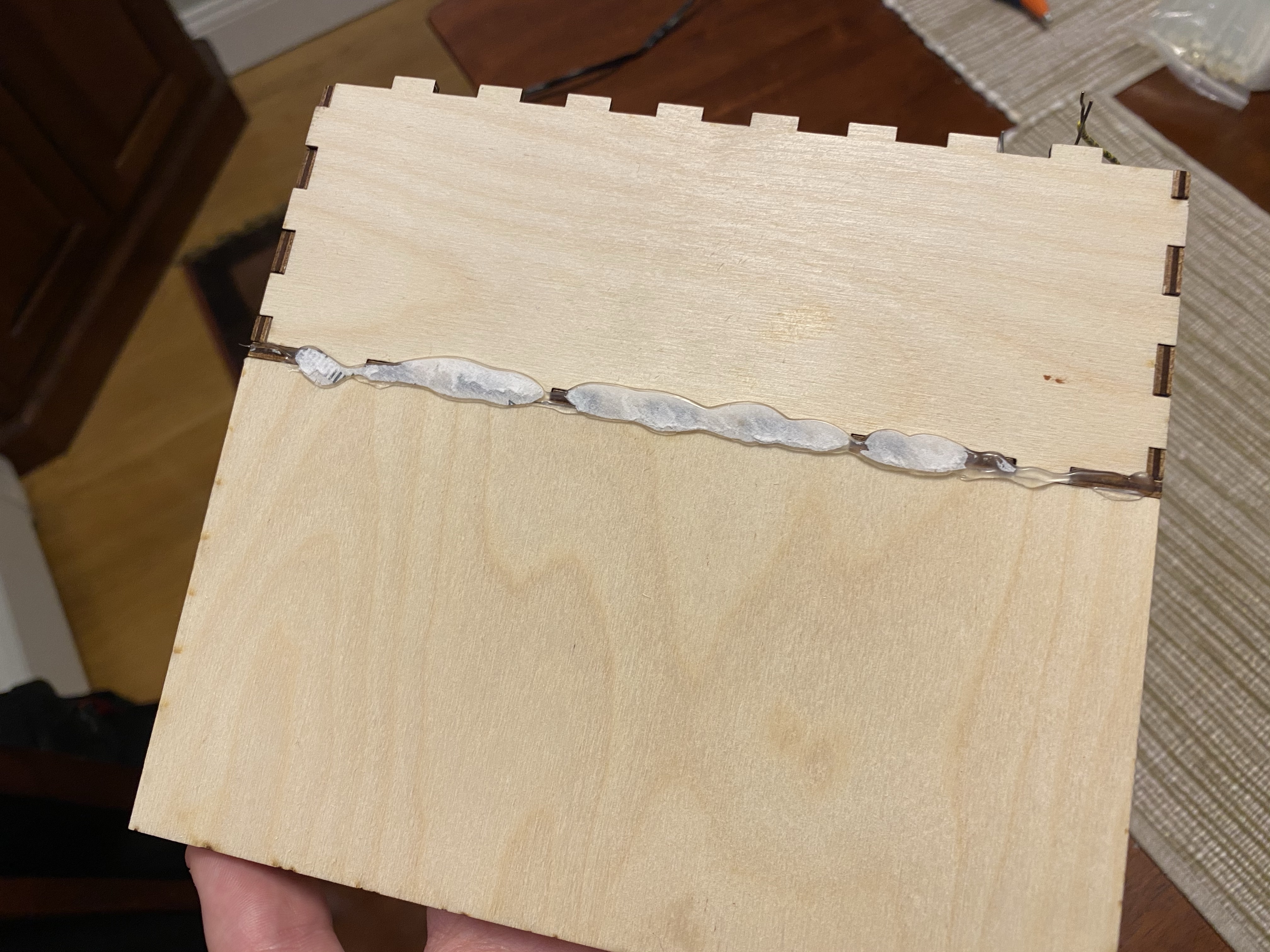
After my test with three keys was successful, I decided to glue most of the box together (excluding the top and back so that I had room to work). First I hot glued the sides and bottom onto the front of the box:
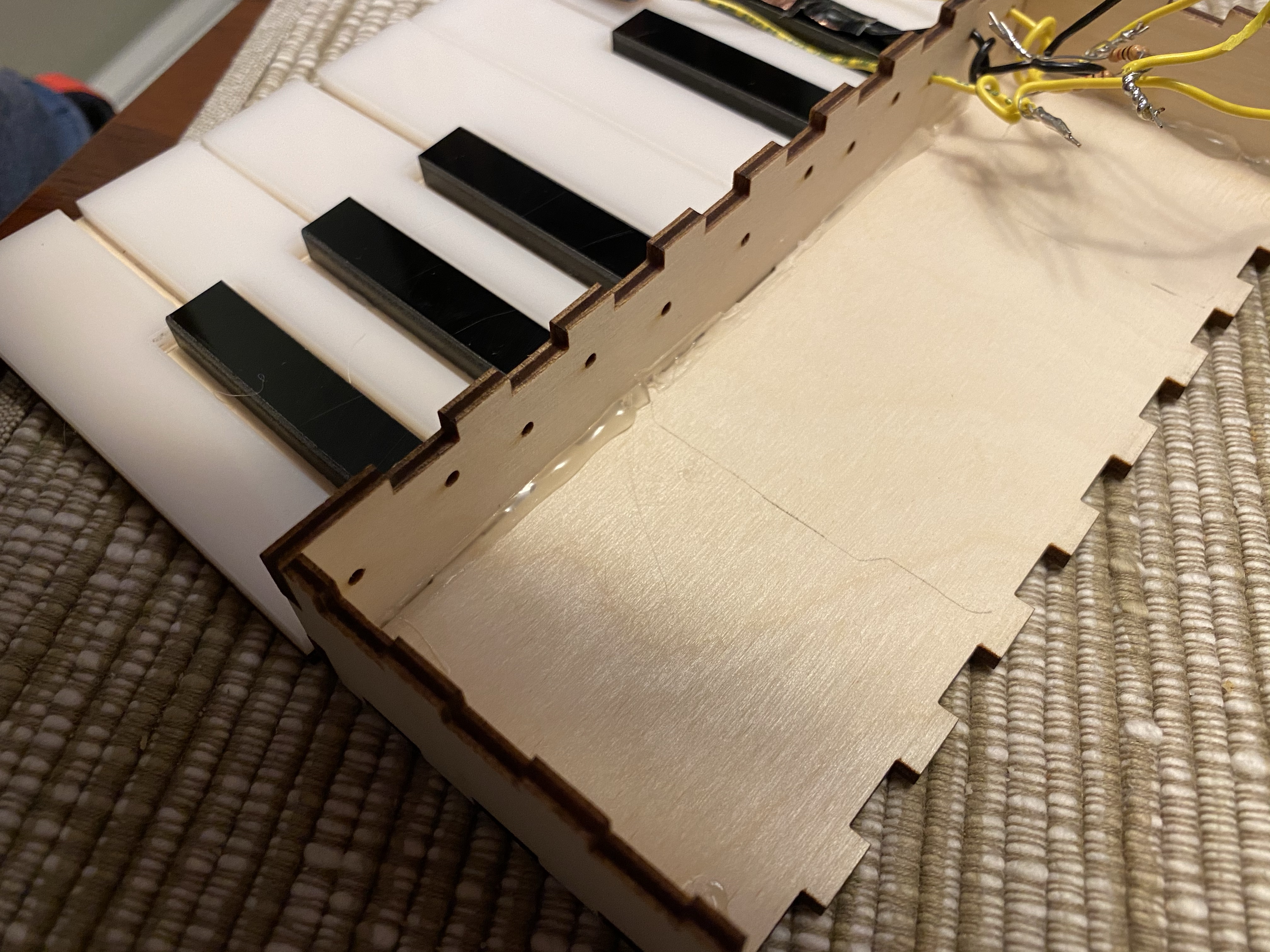
Next I glued the bottom of the platform holding the keys to the bottom of the box (there's paper on it because I pushed the keyboard down onto a spare envelope to flatten out the glue):
With most of the box assembled, it was time to move on to the next section: wiring the remaining keys.
Wiring the Remaining Keys:
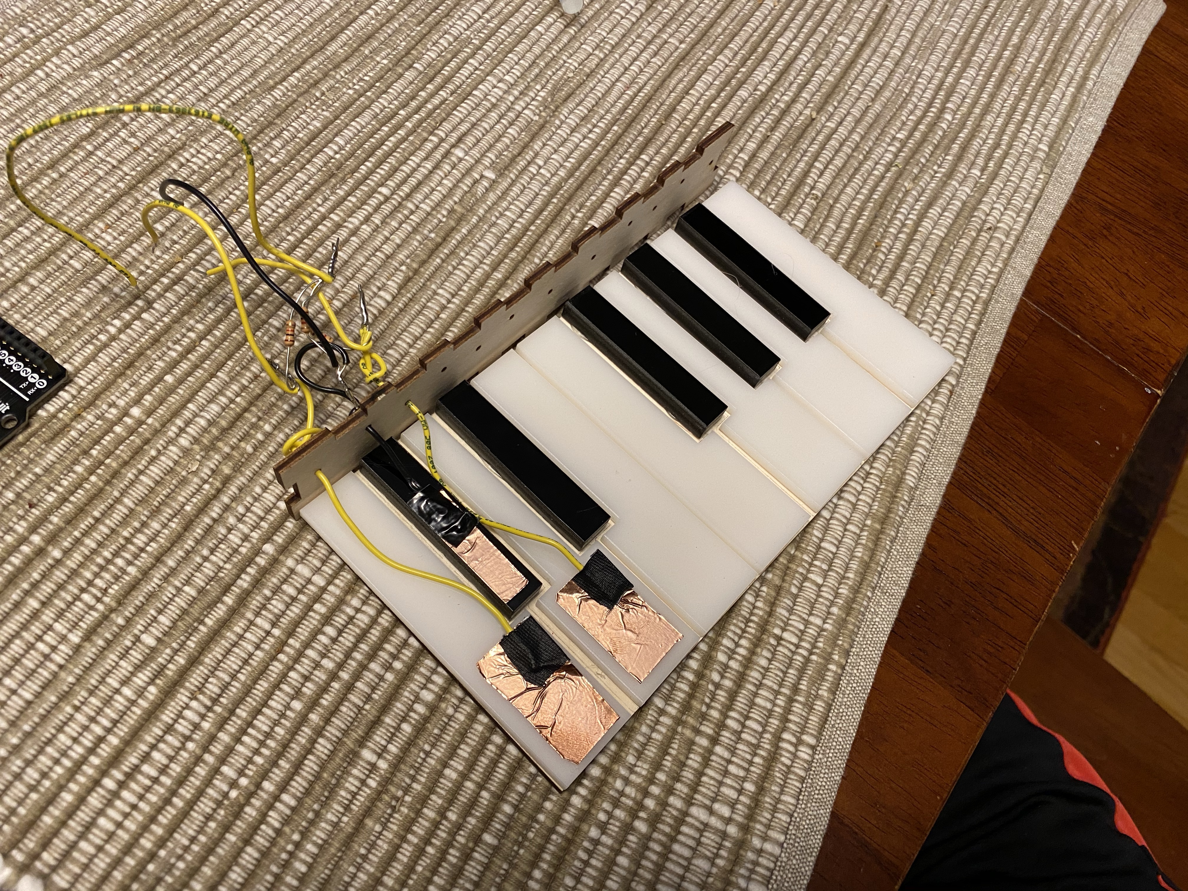
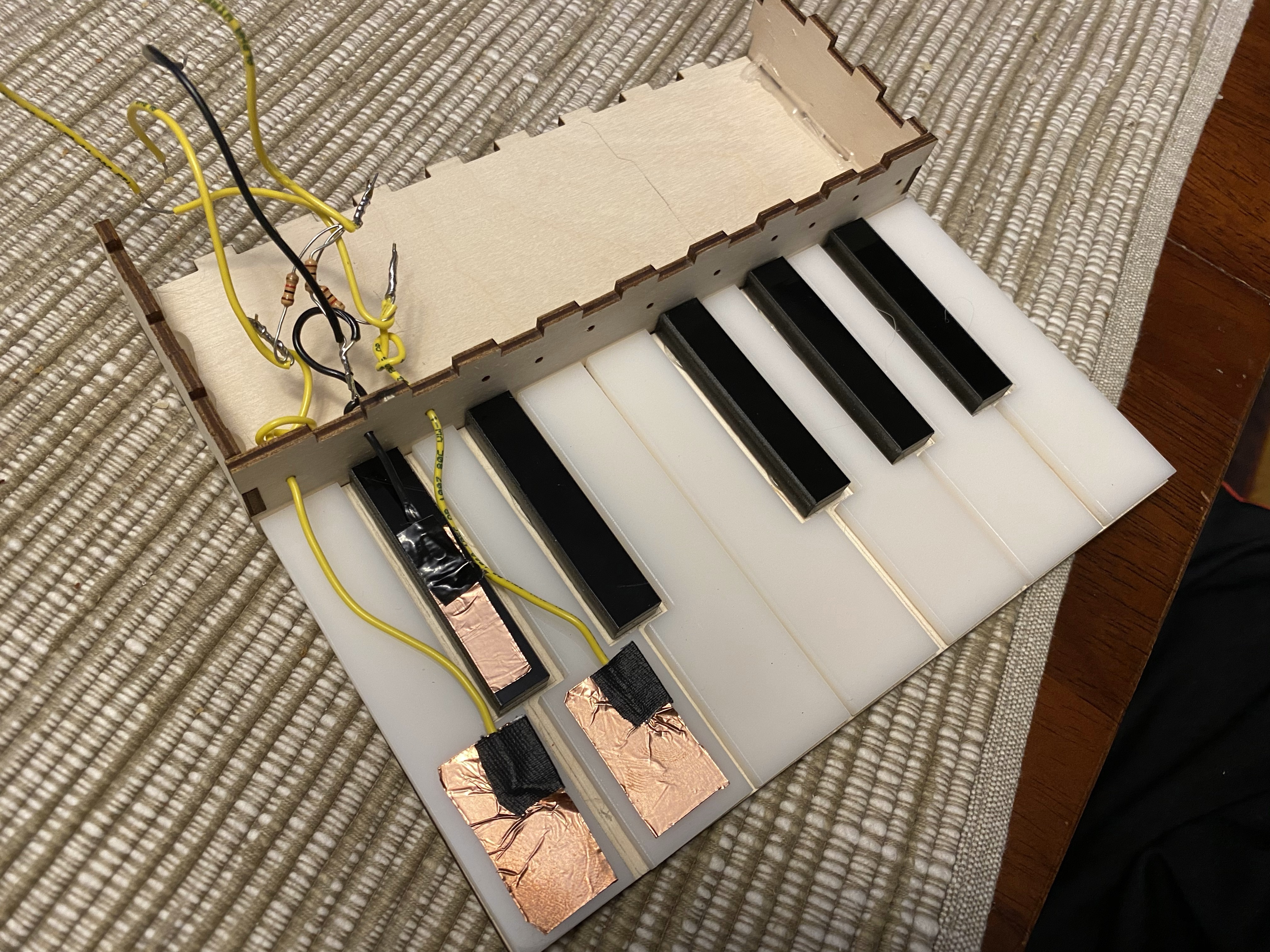
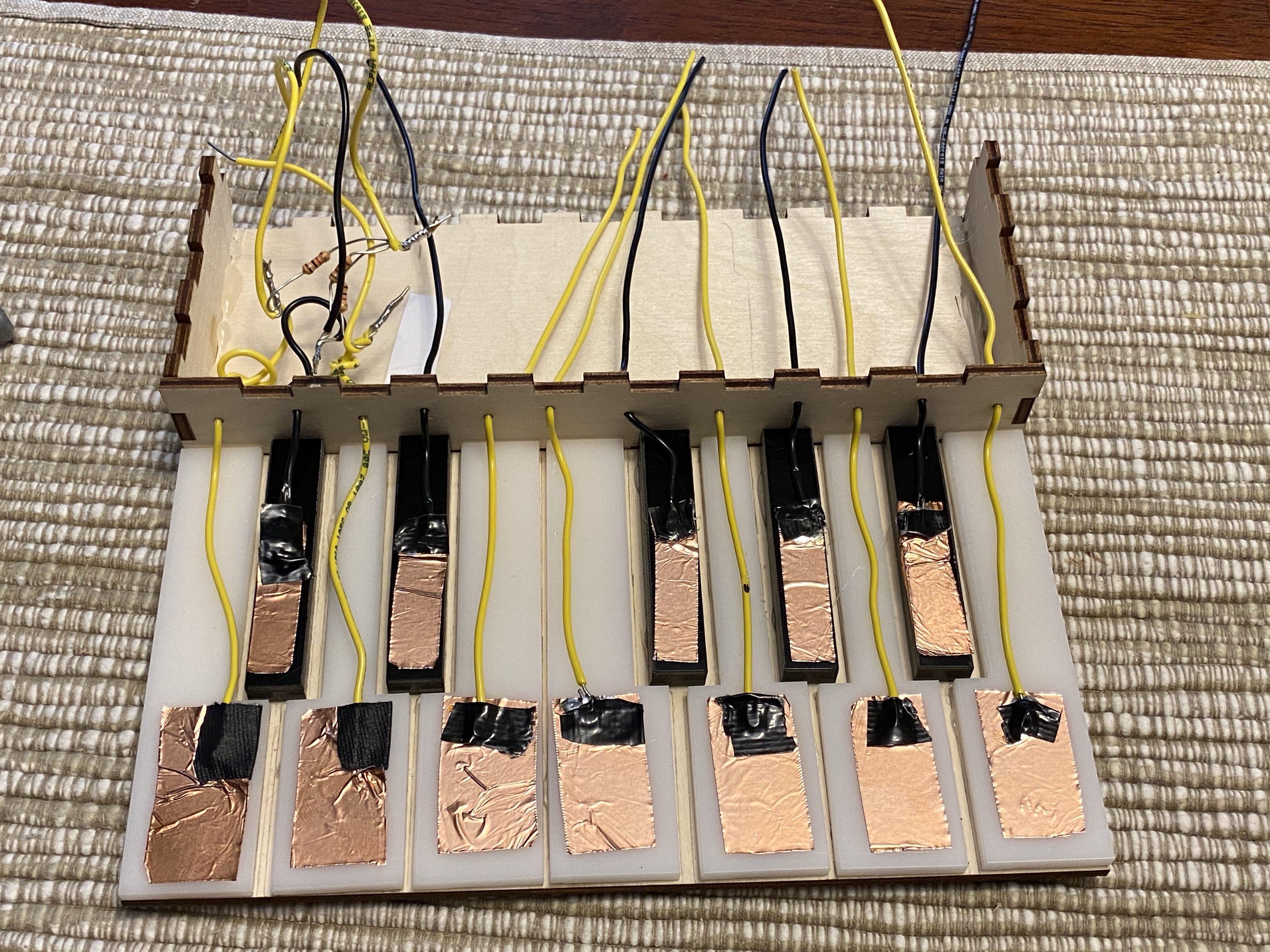
At this point, there were nine remaining keys to wire. I started by repeating the process for the third key I had done earlier: cutting out a piece of copper tape, soldering a wire to it, puting some black tape on the top, taping it down onto the key, and then sticking the wire through the front of the box. I did this for all nine remaning keys, and the result looked like this:.
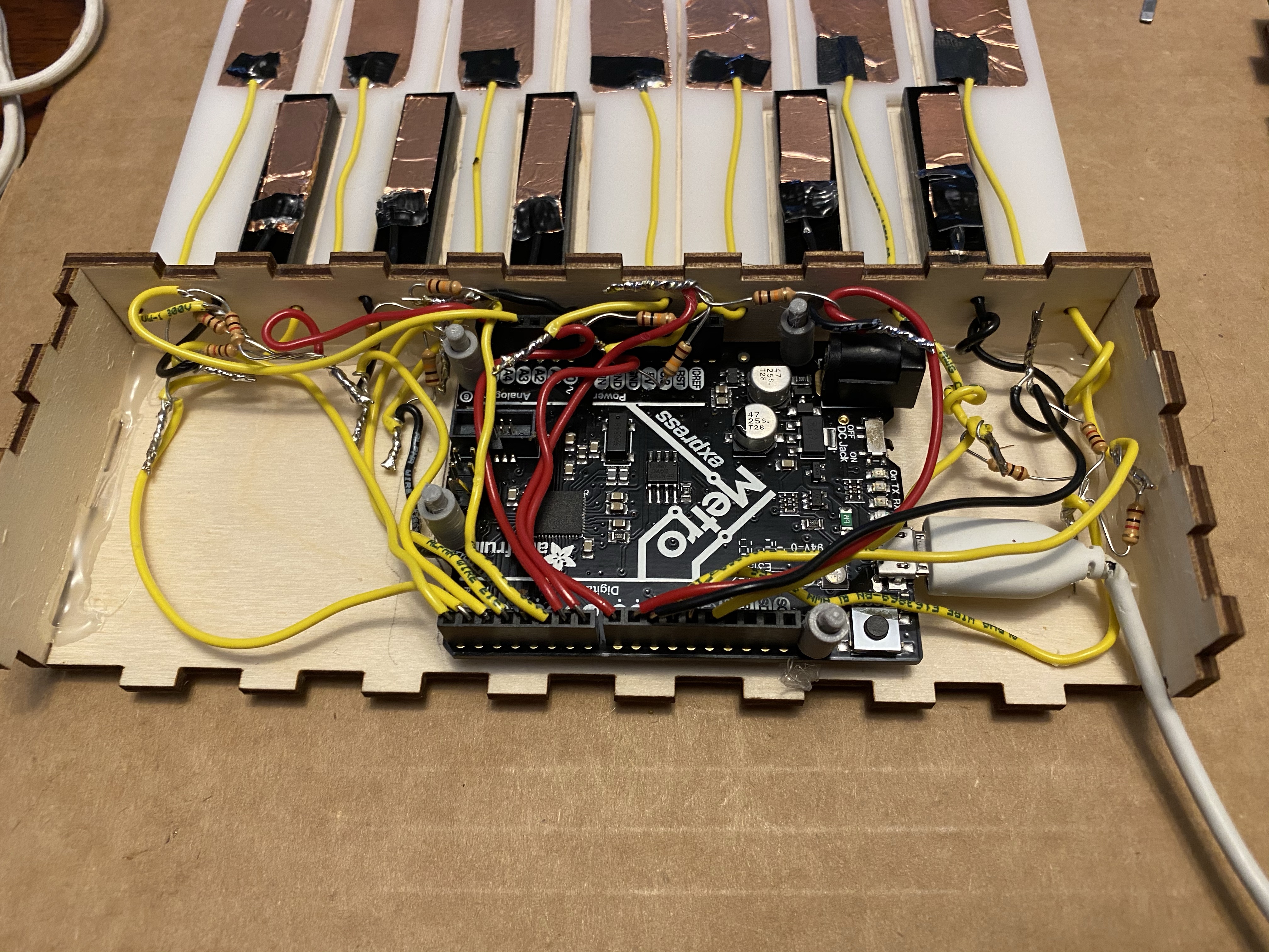
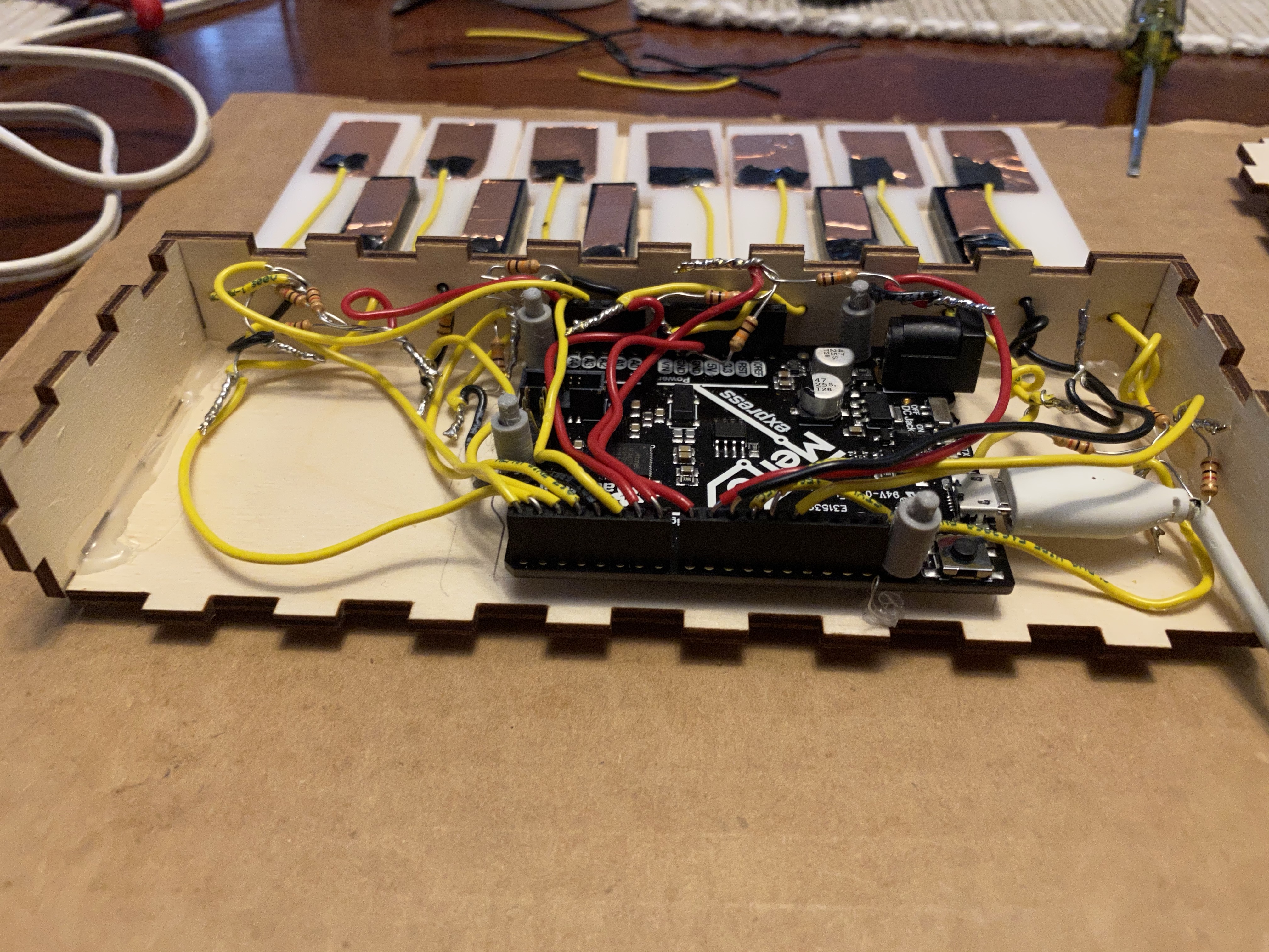
Once these wires were stuck through the box, I repeated the process from before of soldering the wire from the tape, a resistor, and another wire together. Again, I soldered resistors in groups of three to another wire to connect to a charge pin. The only difference here came with the resistors. I didn't have twelve of any resistor, so I knew that I'd have to split the resistance amount up. In the end, six keys had 1k Ω resistors and the other six had 10k Ω resistors. After soldering all the wires together, I sketched out where the metro was going to go and then hot glued it down using the microcontroller pins I had printed. I put the pins in the Metro first and put a bit of glue on the bottom of the pins then quickly placed it on the box to make sure it stuck. Once the Metro was glued down, I plugged in all of the wires to their given pins. Here's the final wiring for the keys:
Attaching and Wiring the Buzzer/Buttons:
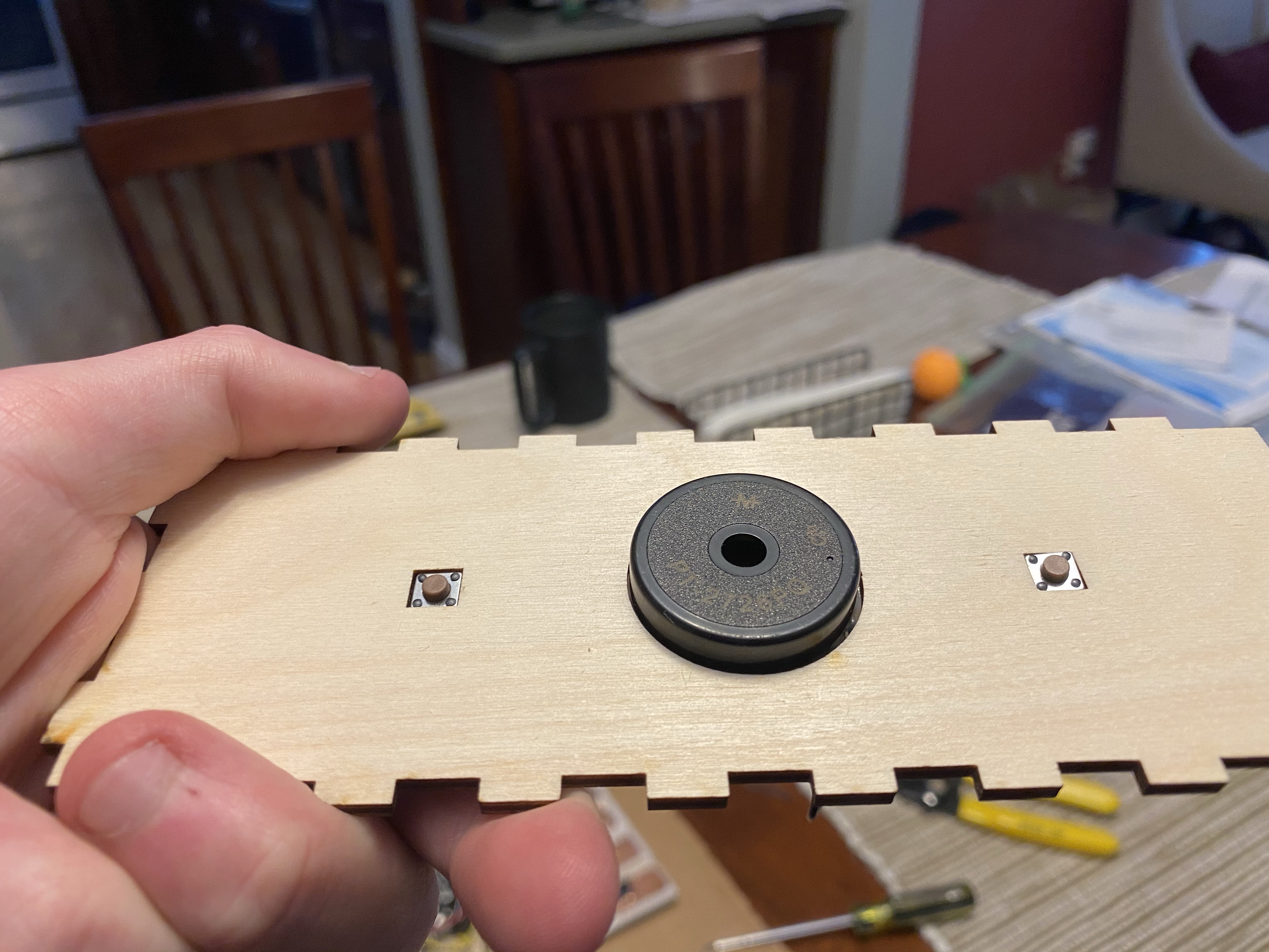
After finishing the wiring for the keys, I moved onto gluing and wiring the buzzer and two buttons. The first thing I did was use hot glue to glue the buttons and buzzer into the corresponding holes in the roof of the box, just as I had designed. After gluing them, I decided it would be best if I crimped the buzzer pin going to ground with another wire to reduce the amount of soldering I needed to do. The result looked like this:
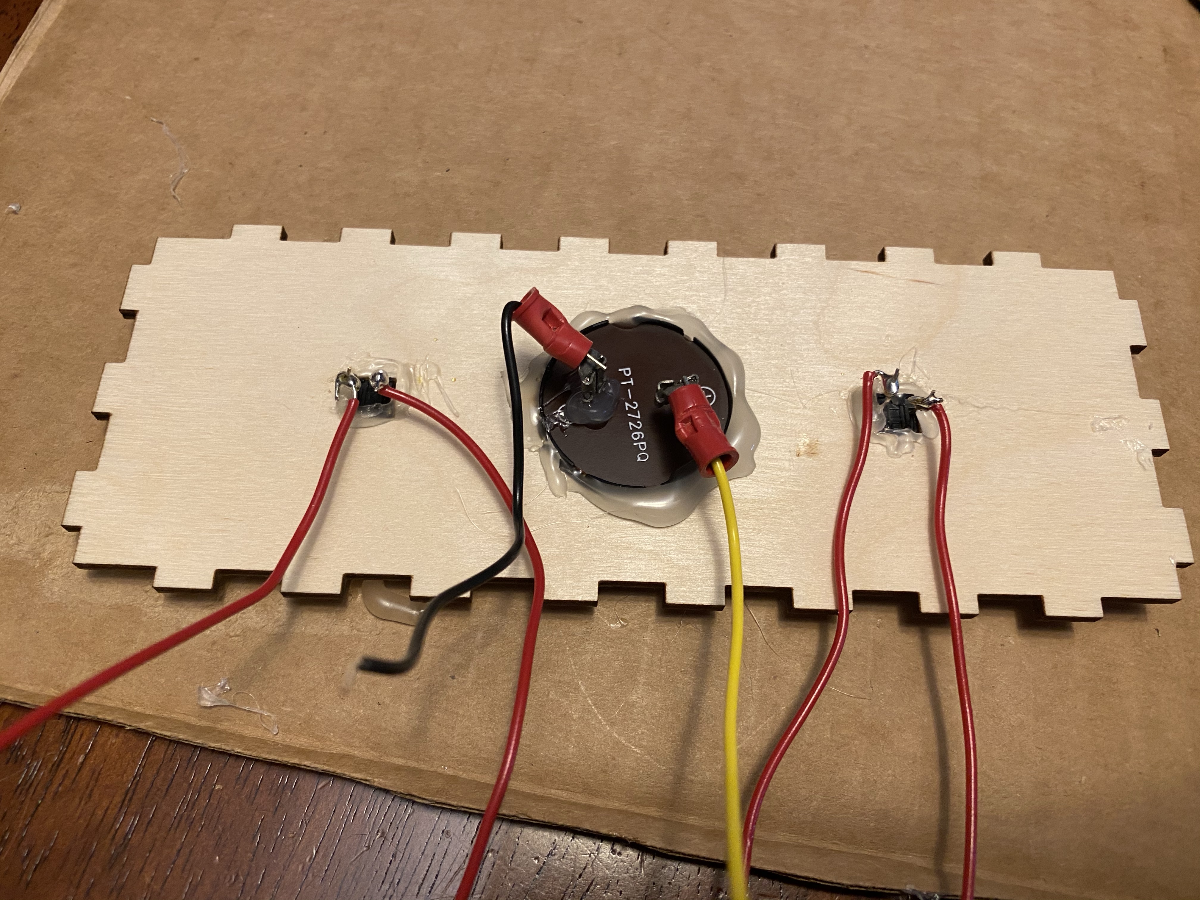
Once I made sure the buzzer and buttons were securely glued down, I moved on to wiring them. First, I used plyers to shape the wires into an oval at the end, which I then placed and tightened around the first button pin. I then repeated this process for the remaining pins. After the wires were in place, I soldered them to the pins, which produced this:
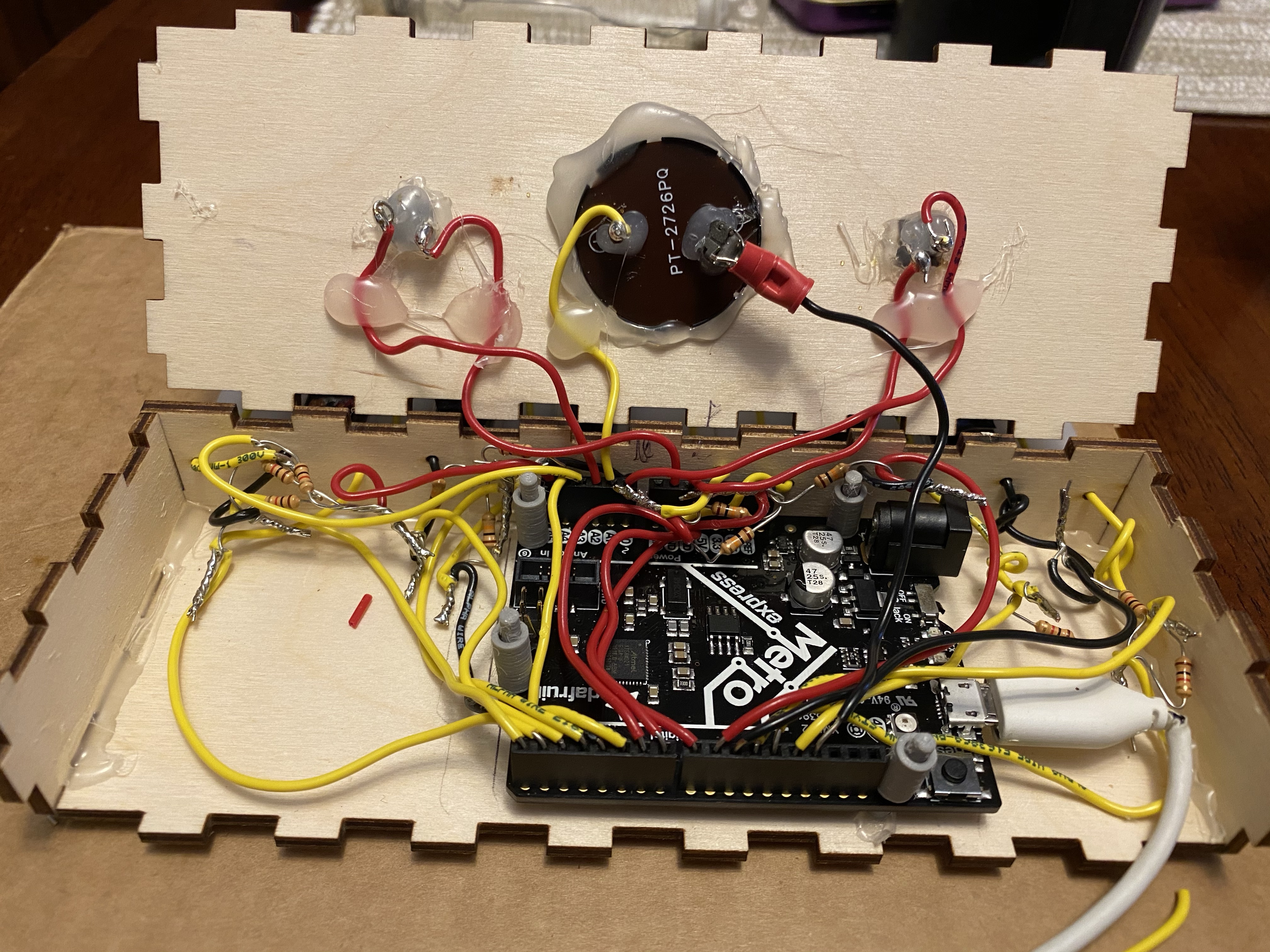
Now that I had the wires soldered on, I moved onto attaching them to the metro. First, I hot glued the wires down on the roos of the box to reduce the stress on the end of the wire, which was most susceptible to breaking. Next, I plugged the wires into their given ports on the metro and connected each button and the buzzer to its own ground, as the board has 3 ground ports. This easily allows me to replace a button or the buzzer if one of them breaks, without having to worry about soldering keeping the three of them attached. The final wiring looked like this:
The Code:
The code for my project is arguably the most important part. I didn't want to make the code just to play a note when I press a piece of copper tape; I wanted it to do more. So I decided to also make it possible to play 2 pre-made songs simply by double clicking a button. In the end, the code was quite lengthy, so I watched this tutorial and learned how to split my code up into different tabs. The first tab contains global variables/constants, the setup() function, and the loop() function. Another tab looks for a button press, and the third and fourth play a song depending on which button was double clicked. I'll explain how the code works (mostly) tab by tab.
Tab 1: The Main Code
The first tab contains the bulk of the code for my project. Early on, I decided to make it possible to change the current octave by pressing the left or right button. Because of that, I made an array for each note with frequencies corresponding to octave using this frequency chart. It's imperative that I mention that the buzzer can't go low enough to play notes in the first octave, so the first element in each array is actually for octave 2; they go up to octave 7. Along with these arrays, I also set the starting octave to 4, which starts on middle C, a great way to orient the piano. Here's the code for this section:
      //Note constants arrays
              //Octave:  2     3     4     5     6       7
              //No octave 1 because the frequencies were too low to be played
      const int C[7] =  {65,  131,  262,  523,  1047,  2093};
      const int CS[7] = {69,  139,  277,  554,  1109,  2217};
      const int D[7] =  {73,  147,  294,  587,  1175,  2349};
      const int DS[7] = {78,  156,  311,  622,  1245,  2489};
      const int E[7] =  {82,  165,  329,  659,  1319,  2637};
      const int F[7] =  {87,  175,  349,  698,  1397,  2794};
      const int FS[7] = {93,  185,  370,  740,  1480,  2960};
      const int G[7] =  {98,  196,  392,  784,  1568,  3136};
      const int GS[7] = {104, 208,  415,  831,  1661,  3322};
      const int A[7] =  {110, 220,  440,  880,  1760,  3520};
      const int AS[7] = {117, 233,  466,  932,  1867,  3729};
      const int B[7] =  {123, 246,  493,  988,  1976,  3951};

      //Initially, the starting octave is 4 (starts on middle C)
      int curOctave = 4;
The next thing I did was define the sensors for each piece of copper tape. I split them up into groups of three, as there are three notes to a charge pin. These are the definitions for the first three notes:
      //Defining sensors for each piece of copper tape. 12 total (1 for each note)
      //Groups of 3 notes attached to one charge pin
      CapacitiveSensor C_sensor = CapacitiveSensor(11, 12); //11 is charge pin.  12 is sense pin.
      CapacitiveSensor CS_sensor = CapacitiveSensor(11, 10);
      CapacitiveSensor D_sensor = CapacitiveSensor(11, 13);
Next, I defined the pin for the buzzer and the pins/starting states for the buttons:
      //Defining the pin for the buzzer
      const int buzzerPin = A1;

      //Defining the pins and states of the buttons
      const int buttonOnePin = A0;
      int buttonOneState = 0;

      const int buttonTwoPin = A2;
      int buttonTwoState = 0;
Those are all the global variables that are used in this tab. Next, I worked on the setup() function. It's relatively simple: I just setup the buzzer pin as output and the button pins as input pullup. I needed to do input pullup since I didn't have any resistors wired to my buttons. Doing so enables the internal pullup resistor in the pin, allowing the button to work properly. I originally didn't know about this, which led to an issue where the button only worked when I touched the pin on the bottom of it, not when I clicked it. I talked to Nathan during lab time and he told me about using input pullup, which fixed the problem. Here's the full setup() function:
      void setup() {
        //Setup buzzer pin mode as output
        pinMode(buzzerPin, OUTPUT);

        //Setup button pin modes as input
        pinMode(buttonOnePin, INPUT_PULLUP);
        pinMode(buttonTwoPin, INPUT_PULLUP);
      }
Next I have the loop() section of my code, which contains most of the actual note playing. I started it by defining the sensor values for each note (below are the first three):
      long C_sensorValue = C_sensor.capacitiveSensor(1000);
      long CS_sensorValue = CS_sensor.capacitiveSensor(1000);
      long D_sensorValue = D_sensor.capacitiveSensor(1000);
Next, I reassign the button state variables to the current state of each button, and then call the function that checks for a button press:
      //Get the state of each button
      buttonOneState = digitalRead(buttonOnePin);
      buttonTwoState = digitalRead(buttonTwoPin);

      //Changing the octave if a button is pressed (button 1 lowers it, b2 raises it), or playing a song if a button is double-clicked
      checkForButtonPress();
I'll explain more about the button press function in the next section.
After checking for a button press, I have the final part of my loop: playing the note. It's a series of if/else if statements in which a note is played if the sensor value is greater than 0, which I determined was the appropriate threshold. When calling the tone() function, I set the frequency to the current octave's index of the note array minus 2. The reason I subtract two is because the second octave on the piano is the first index of each note array, which is called by position [0]. I have the buzzer play the note for 200 ms when the tape is pressed, which I determined to be a good amount through trial and error.
      //Series of if/else if statments that play a note if it's being held down
      if (C_sensorValue > 0) {
        tone(buzzerPin, C[curOctave - 2], 200);   //cur octave - 2 since the array starts with C2, but the index is 0
        delay(200);
      }

      else if (CS_sensorValue > 0) {
        tone(buzzerPin, CS[curOctave - 2], 200);
        delay(200);
      }

      else if (D_sensorValue > 0) {
        tone(buzzerPin, D[curOctave - 2], 200);
        delay(200);
      }

      //REST OF NOTES FOLLOW BELOW (not included for space purposes)
Tab 2: Checking For A Button Press
This tab has just one function: checkForButtonPress(), which is called in the loop function of the first tab. The function first checks if button one (the left button) was pressed. If so, it assigns currentMillis to the result of the millis() function. I then have a timer to detect whether or not the button has been double clicked. If the current ms minus the previous ms is greater than 200 ms, the previous ms variable is assigned to the value of the current ms. As an aside, the previousMillis variable was defined in the first tab:
unsigned long previousMillis = 0; //Stores last time a Button was pressed
If it's been over 200 ms and the button wasn't pressed again, it delays by 150 ms to allow time for releasing the button. Otherwise, it'll try to change the octave by more than 1. Next, it re-checks the button state to see if it's been released or not. If the current octave isn't 2 (the lowest it can go) and the button isn't pressed, it decreases the octave by one. Outside of the timer if statement, there's an else if in which, if the button has been double clicked, it plays Rondo Alla Turca, a Mozart song I played on the piano a few years ago (I'll explain more in the next section). If the first button wasn't clicked, however, it does this same process with the second button if the second one was pressed. The only changes are that it looks to see if the current octave is 7 (highest octave) before increasing the octave by one, and instead of playing Rondo Alla Turca it plays Happy Birthday. Here's the whole tab:
      //Function to check for octave change (button pressed)
      void checkForButtonPress() {
        //Only does an action if button 1 is pressed
        if (buttonOneState == LOW) {
          unsigned long currentMillis = millis();

          //Timer
          if (currentMillis - previousMillis >= 200) {
            previousMillis = currentMillis;

            delay(150);
            buttonOneState = digitalRead(buttonOnePin);   //Re-gets state of button to check if it's still pressed or not

            //Decreases the octave if it's not already the lowest octave and the button hasn't been double clicked
            if (curOctave != 2 && buttonOneState != LOW) {
              curOctave--;
            }
          }

          //If the button HAS been double clicked, it plays Rondo Alla Turca
          else if (buttonOneState == LOW) {
             playRondoAllaTurca(150);
          }
        }

        //Only does an action if button 1 wasn't pressed and button 2 was pressed
        else if (buttonTwoState == LOW) {
          unsigned long currentMillis = millis();

          if (currentMillis - previousMillis >= 200) {
            previousMillis = currentMillis;

            delay(150);
            buttonTwoState = digitalRead(buttonTwoPin);

            //Increases the octave if it's not already the highest octave and the button hasn't been double clicked
            if (curOctave != 7 && buttonTwoState != LOW) {
              curOctave++;
            }
          }

          //If the button HAS been double clicked, it plays Happy Birthday
          else if (buttonTwoState  == LOW) {
             playHappyBirthday(120);
          }
        }
      }
Tab 3: Rondo Alla Turca
This tab is used solely when the left button is double clicked to play Rondo Alla Turca. The main function takes beats per minute as a parameter, so the first thing I did was calculate the note lengths in ms. For example, to calculate of the duration of a quarter note, I took 60,000 (number of ms in a minute) and divided it by the bpm. I defined global variables in the first tab to hold the duration of each note:
      //Initializing note lengths for the different notes in the songs
      //Allows me to change the length of all notes of the same type (ie. all quarter notes) without having to change each individual one
      int halfNote;
      int quartNote;
      int dotEigthNote;
      int eigthNote;
      int sixteenthNote;
      int thirtySecondNote;
And then in main function of the Rondo Alla Turca tab, I calcluated the duration of each note, and then I have it play the first section twice (since there's a repeat) and then the second section:
      void playRondoAllaTurca(int bpm){
        quartNote = (int) ((float) 60000 / bpm);
        halfNote = quartNote * 2;
        eigthNote = (int) (quartNote / 2);
        sixteenthNote = (int) ((float) quartNote / 4);
        thirtySecondNote = (int) ((float) sixteenthNote / 2);

        rondoSectionOne(bpm);
        rondoSectionOne(bpm);

        rondoSectionTwo(bpm);
      }
As you can see, each section of the song has it's own function. Both are structured in the same way. There's an array of integers called notes, which holds the series of notes in the section. For example, calling middle C in the array is C[2]. It's 2 because octave 4 is the 2nd index of the notes arrays in the main tab. There's also a noteDurations array which holds the duration of each note in the secton. Next, I wanted to determine the length of the array so that I could use it in the for loop (I'll explain the loop next). To do so, I read this tutorial that explained how to find the length of an array. I thought it would be simply calling notes.length() like in Java, but it's much more complicated in C. I have to divide the size of the array in bytes by the size of the first element, determining the length. After determining the length, I have a for loop that loops through each element in the array and plays the current index of notes for a duration of the current index of noteDurations, and then delays by the note duration. I repeated this for the second section, and it worked! Here's the final code:
      //Function to play Rondo Alla Turca
      void playRondoAllaTurca(int bpm){
        quartNote = (int) ((float) 60000 / bpm);
        halfNote = quartNote * 2;
        eigthNote = (int) (quartNote / 2);
        sixteenthNote = (int) ((float) quartNote / 4);
        thirtySecondNote = (int) ((float) sixteenthNote / 2);

        rondoSectionOne(bpm);
        rondoSectionOne(bpm);

        rondoSectionTwo(bpm);
      }

      //First Section of Rondo Alla Turca
      void rondoSectionOne(int bpm){
        int notes[44] = {B[2], A[2], GS[2], A[2], C[3]};   //Only the first 5 notes, the rest was too long and repetitive for it to be necessary

        int noteDurations[44] = {sixteenthNote, sixteenthNote, sixteenthNote, sixteenthNote, quartNote};   //Again, only the first 5 notes

        //Determining array length
        int notesLength = sizeof(notes) / sizeof(notes[0]);

        //Looping through the arrays and playing each note
        for (int i = 0; i < notesLength; i++){
          tone(buzzerPin, notes[i], noteDurations[i]);
          delay(noteDurations[i]);
        }
      }

      //Second Section of Rondo Alla Turca
      void rondoSectionTwo(int bpm){
        int notes[81] = {E[3], F[3], G[3], G[3], A[3]};

        int noteDurations[81] = {eigthNote, eigthNote, eigthNote, eigthNote, sixteenthNote};

        //Determining array length
        int notesLength = sizeof(notes) / sizeof(notes[0]);

        //Looping through the arrays and playing each note
        for (int i = 0; i < notesLength; i++){
          tone(buzzerPin, notes[i], noteDurations[i]);
          delay(noteDurations[i]);
        }
      }
Tab 4: Happy Birthday:
The last tab contains a function to play Happy Birthday. It's structured in the same way as Rondo Alla Turca, so there's not much to explain. Here's the code:
      void playHappyBirthday(int bpm){
        //60,000 because there's 60,000 ms in a minute
        quartNote = (int) ((float) 60000 / bpm); //At 120 BPM a quarter note will have a duration of 500 ms
        halfNote = quartNote * 2;
        dotEigthNote = (int) (quartNote * 0.75);
        sixteenthNote = (int) ((float) quartNote / 4);

        //Array of notes for Happy Birthday
        int notes[] =   int notes[] = {C[2], C[2], D[2], C[2], F[2]};   //Like above, I'm only displaying the first 5 notes

        //Note durations
        int noteDurations[25] = {dotEigthNote, sixteenthNote, quartNote, quartNote, quartNote};

        //Determining array length
        int notesLength = sizeof(notes) / sizeof(notes[0]);

        //Looping through the arrays and playing each note
        for (int i = 0; i < notesLength; i++){
            tone(buzzerPin, notes[i], noteDurations[i]);
            delay(noteDurations[i]);
        }
      }
I broke up the code a bunch and didn't include all of it (for example, only showing 3 notes instead of all 12). The ZIP folder with all of the code can be downloaded here
What I Learned:
Throughout this final project, I learned so much, from more about Fusion 360 to soldering to video editing with OpenShot. So, like before, I'm splitting this section up into subsections to better explain what I learned.
Design:
- I learned more about how to insert an SVG and trace premade shapes over it (like I did with the holes in the box).
- How to design pins to fit properly with appropriate tolerance.
Building:
- Originally, I had no clue how to design a circuit that could fit multiple pieces of tape into one charge pin. Learning more about how the circuit works and sketching it out helped me understand the fundamental knowledge behind circuits and capacitence.
- How helpful it is to determine which wire plugs into each pin beforehand; doing so made the wiring process significantly easier
- How to solder. I had never done it before but I feel much more comfortable after the sheer amount of soldering I did for the keyboard
- The importance of planning out each step of the building process ahead of time. Originally, I wanted to do all twelve wires at once but, in talking to Nathan, realized it wouldn't be smart to spend all that time wiring and soldering without knowing if the circuit actually worked, which is why I did an original test with three keys.
Code:
- How to use an arrays for the note frequencies to make it easier to call and play a certain note.
- How to use delta timing to check for a double click on the buttons
- The importance of using INPUT_PULLUP for the buttons since I didn't wire them to a resistor
- How to split up the notes and note durations for my premade songs into seperate arrays and then play them using a for loop
- How to split my code up into tabs to make it more organized. Before I made tabs, my code was really cluttered and it was hard to find specific sections at times. Using tabs was quite helpful.
Video Editing:
- I watched this OpenShot tutorial in which I learned a lot about the basics and how to make my final video better than just raw footage.
- How to properly upload a video to YouTube, which isn't something I've done before
Mistakes and How to Fix Them:
- Making the box too small: I modeled the box to fit the length of my keyboard and the width of the Metro. In doing so, I had very little room to fit all of the wires, especially because of how much space the soldered parts took up, as they couldn't be bent to make room. This should have been an easy fix IF we had had access to the lab. Unfortunately, we don't, so I had to make do with the box that I had.
- Not testing the capacitence beforehand: In the end, my keyboard is only fully functioning when plugged into my computer's keyboard. When I tried plugging it into the 5V battery pack from my kit, or into a wall outlet, or even into another laptop, only the keys with the 10k Ω resitors worked; the ones with 1k Ω resistors didn't work. I used the Serial monitor to look at the readings. On my computer where the whole piano worked, the 1k's were getting a reading of 10-100, and the ones with 10k were getting upwards of 450. But when I plugged it into anything else, the 1k's stayed at 0. This was a capacitence issue that I hadn't even thought of; I just assumed that 1k resistors would work well. It may seem that I could have fixed this by simply replacing the 1k resistors with stronger ones. However, I was tinkering with my code until just before filming, so I had never tried my piano in another outlet besides the one in my computer. By that point, all the resistors were soldered on and I didn't have time to redo half my project. It's unfortunate, but I'm really happy with my solution of placing my computer's keyboard on the ground and connecting to the piano from there. You can't even tell that there's a keyboard in the video.
- Letting my dog near my project: Oh boy, this is a fun one. For my recording, I had my keyboard plugged into my computer's keyboard through a long USB, so the computer keyboard was on the ground under my desk. At this point, I was getting ready to film and my dog decided it was a great idea to sit under my desk. When I stood up to film, he took it as "oh we're going on a walk", raced out from under my desk, and got caught on my USB cable. It yanked my piano off the desk, which I thankfully caught, but it ripped off the back of the box, disconnected about ten wires, and damaged the USB port on the Metro. It took me more takes than it should've to film because the piano kept disconnecting (and it's why the USB is plugged in weirdly at the end of my video). Thankfully, my project wasn't broken and I was still able to film exactly what I wanted.